Supercharge Your Innovation With Domain-Expert AI Agents!

Steaming room utilizing solar energy

A technology of solar energy and sweat steaming, applied in the field of sweat steaming room, can solve problems affecting customers' physical and mental health, waste of manpower and material resources, lack of oxygen in sweat steaming room, etc., achieve timely removal of toxic and harmful gases, convenient installation and construction, and solve air turbidity Effect

Active Publication Date: 2018-01-12
GUANGXI GUOBO TECH CO LTD
View PDF5 Cites 0 Cited by
  • Summary
  • Abstract
  • Description
  • Claims
  • Application Information

AI Technical Summary

Problems solved by technology

[0002] In the cold winter, sunshine is very important. People hope to have sunshine everywhere. In addition, people often perform sweat steaming in order to eliminate toxins in the body. However, traditional sweat steaming rooms mostly use heating, electric heaters, coal stoves or direct combustion. Charcoal is used to increase the internal temperature of the sweat steaming room. Due to the above measures for heating, it not only causes a waste of manpower and material resources, but also a large amount of pollutants are discharged into the atmosphere, causing air pollution. At the same time, direct burning of charcoal or briquettes is likely to cause carbon monoxide poisoning, and Charcoal burning consumes oxygen, which can easily cause hypoxia inside the steam room, which in turn affects the physical and mental health of customers. Because the traditional steam room adopts a brick structure and is usually connected to the bathroom, not only the lack of sunlight, but also the humid environment causes the steam room Bacteria grow inside, and the traditional steam room has a single structure, which makes it difficult to meet the requirements of customers for both steaming and sunbathing

Method used


Image

  • Steaming room utilizing solar energy
  • Steaming room utilizing solar energy
  • Steaming room utilizing solar energy

Examples


Embodiment

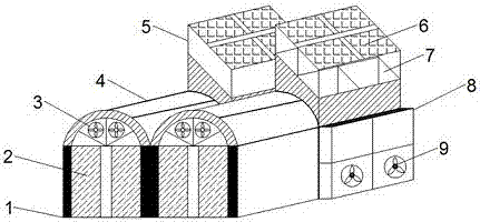
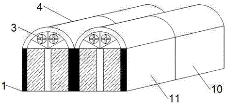
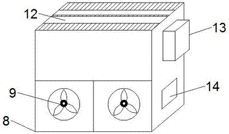
[0025] see figure 1 , figure 2 , image 3 with Figure 4 , the present invention provides a technical solution: a sweat steaming room utilizing solar energy, including a solar support 5 and a main frame 4, and a plurality of photovoltaic modules 6 are installed above the solar support 5, and since the photovoltaic modules 6 are arranged, the The energy source of the sweat steaming room is guaranteed, reducing the utilization of charcoal and other energy sources, thereby realizing clean energy utilization, reducing waste gas emissions, and protecting the environment. There is a battery pack inside, and the battery pack stores the electric energy generated by the photovoltaic module 6 for later use. Meanwhile, the photovoltaic module 6 provides energy for the electrical equipment inside the sweat steaming room 10 . Steaming room 10, the right side of said sweating room 10 is provided with incubator 8, and the front of incubator 8 is provided with air intake fan 9, and air in...


PUM


Abstract

The invention discloses a steaming room utilizing solar energy. The steaming room comprises solar brackets and main body frames; the upper surface of each solar bracket is provided with a plurality ofphotovoltaic assemblies, and storage batteries are arranged under the photovoltaic assemblies; meanwhile, steaming room bodies are arranged under the solar brackets, the right sides of the steaming room bodies are provided with heating boxes, the front faces of the heating boxes are provided with air inlet fans, and heating slices are arranged in the heating boxes; door frames are arranged on thefront portions of the main body frames, the upper portions of the door frames provided with exhaust fans, and meanwhile transparent glass is installed at the top of each main body frame; and the topsof rest areas are provided with glass, accordingly, clients can bathe in the sunshine during resting, the heating boxes cooperate with the photovoltaic assemblies to supply enough heat to the steaming room bodies, and the enough steaming temperature can be achieved for the clients. The steaming room adopts a solar heating mode, the wood charcoal utilization amount is greatly reduced, energy saving, environment friendliness and safety are achieved, pollution is avoided, and meanwhile manpower input is reduced, so that the steaming room is worthy of popularization.

Description

technical field [0001] The invention relates to the technical field of solar energy utilization, in particular to a sweat steaming room utilizing solar energy. Background technique [0002] In the cold winter, sunshine is very important. People hope to have sunshine everywhere. In addition, people often perform sweat steaming in order to eliminate toxins in the body. However, traditional sweat steaming rooms mostly use heating, electric heaters, coal stoves or direct combustion. Charcoal is used to increase the internal temperature of the sweat steaming room. Due to the above measures for heating, it not only causes a waste of manpower and material resources, but also a large amount of pollutants are discharged into the atmosphere, causing air pollution. At the same time, direct burning of charcoal or briquettes is likely to cause carbon monoxide poisoning, and Charcoal burning consumes oxygen, which can easily cause hypoxia inside the steam room, which in turn affects the p...

Claims


Application Information

Patent Timeline
IPC IPC(8): E04H1/12A61H33/06A61N5/06
Inventor 马昭键闫树亮梁文蒙献芳
Owner GUANGXI GUOBO TECH CO LTD
Features
  • R&D
  • Intellectual Property
  • Life Sciences
  • Materials
  • Tech Scout
  • Unparalleled Data Quality
  • Higher Quality Content
  • 60% Fewer Hallucinations
Learn More