[0018] The technical solutions in the embodiments of the present invention will be clearly and completely described below in conjunction with the accompanying drawings in the embodiments of the present invention. Obviously, the described embodiments are only a part of the embodiments of the present invention, rather than all the embodiments. Based on the embodiments of the present invention, all other embodiments obtained by those of ordinary skill in the art without creative work shall fall within the protection scope of the present invention.
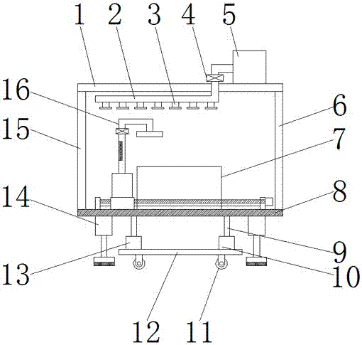
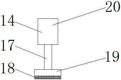
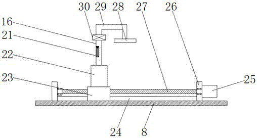
[0019] See Figure 1~3 In the embodiment of the present invention, an environmentally friendly textile machine with shock absorption and cotton dust absorption functions includes a top plate 1, a water guide pipe 2, a spray head 3, a water storage tank 5, a first support rod 6, a textile machine body 7, and a bottom plate 8. Universal wheel 11, base 12, hydraulic telescopic rod 13, shock absorption device 14, second support rod 15 and cotton dust absorbing device 16, said bottom plate 8 is fixedly mounted with a textile machine body 7 at the top, and bottom of said bottom plate 8 A hydraulic telescopic rod 13 is arranged symmetrically. The hydraulic telescopic rod 13 includes a first hydraulic cylinder 10 and a first hydraulic rod 9. The first hydraulic cylinder 10 is fixedly mounted on the top of the base 12, and the first hydraulic cylinder 10 is hydraulically connected to the first hydraulic cylinder. Hydraulic rod 9, the top of the first hydraulic rod 9 is fixedly installed at the bottom of the bottom plate 8. The hydraulic telescopic rod 13 is used to adjust the height of the bottom plate 8, thereby realizing the adjustment of the height of the textile machine body 7 to meet the operation of different heights The use of personnel improves the practicability of the equipment. The bottom of the base 12 is symmetrically installed with universal wheels 11, and the free movement of the equipment is realized by arranging the universal wheels 11 at the bottom of the base 12, which improves the practicability of the equipment;
[0020] A shock-absorbing device 14 is symmetrically arranged at the bottom of the bottom plate 8. The shock-absorbing device 14 includes a second hydraulic rod 17, a second hydraulic cylinder 20, a shock-absorbing material pad 18 and a pressure plate 19, and the second hydraulic cylinder 20 is fixedly installed At the bottom of the bottom plate 8, a second hydraulic cylinder 20 is hydraulically connected to a second hydraulic rod 17. A pressure plate 19 is fixedly installed at the bottom of the second hydraulic rod 17, and the second hydraulic cylinder 20 is used to drive the second hydraulic rod 17 to move downward to drive the pressure plate 19 moves down to contact the ground, and the friction between the pressure plate 19 and the ground is used to realize the fixation of the equipment on the ground. The bottom of the pressure plate 19 is fixedly provided with a shock-absorbing material pad 18, and the shock-absorbing material pad 18 is The rubber material is used to absorb the vibration generated by the equipment when the shock-absorbing material pad 18 is set to avoid excessive vibration of the equipment and damage the equipment itself, which improves the practicability of the equipment. At the same time, the shock-absorbing material pad 18 is further provided. Increase the friction between the pressure plate 19 and the ground, thereby further improving the effect of equipment fixing;
[0021] A cotton waste absorbing device 16 is provided on the top of the bottom plate 8. The cotton waste absorbing device 16 includes a permanent magnet 21, a cotton waste collection box 22, a slider 23, a slide rail 24, a motor 25, a limit plate 26, a screw 27, The absorbing cover 28, the pipe 29 and the exhaust fan 30, the slide rail 24 is fixedly arranged on the top of the bottom plate 8, and the top of the bottom plate 8 is located at the two ends of the slide rail 24. The limit plate 26 is fixedly installed on the slide rail 24. Block 23, the top of the sliding block 23 is fixedly installed with a cotton waste collection box 22, the feed port of the cotton waste collection box 22 is connected to the discharge port of the absorption cover 28 through a pipe 29, and the pipe 29 is installed with a suction The machine 30 uses the exhaust fan 30 to make the cotton waste generated during the operation of the textile machine body 7 enter the pipe 29 through the absorption cover 28 and then further enter the cotton waste collection box 22 to prevent the cotton waste generated during the operation of the textile machine body 7 from floating in the air While polluting the workshop environment, it also affects the health of the workshop operators and improves the practicability of the equipment. The pipe 29 is provided with a permanent magnet 21. The permanent magnet 21 is used to prevent cotton dust entering the pipe 29. The ferrous impurities are adsorbed to realize the separation of ferrous impurities and cotton chips. The slider 23 is provided with a threaded through hole for threaded connection with the screw 27, and one end of the screw 27 is rotatably mounted on a bearing seat On the limit plate 26 at one end of the slide rail 24, the other end of the screw 27 is connected to the output shaft of the motor 25 through a coupling. The motor 25 is fixedly installed on the limit plate 26 at the other end of the slide rail 24 by bolts. The rotation of the motor 25 realizes the movement of the slider 23 on the slide rail 24, thereby expanding the absorption range of the absorption cover 28, and realizing the absorption of cotton scraps in the air at different positions in the workshop, which improves the absorption of the absorption cover 28 to the workshop. The absorbing effect of cotton chips in the air improves the practicability of the equipment;
[0022] A plurality of spray heads 3 are arranged above the textile machine body 7, and the input end of the spray head 3 is connected to the outlet of the water storage tank 5 through the water guide tube 2. The water storage tank 5 is fixedly installed on the top of the top plate 1. The top plate 1 The two ends are respectively fixedly installed on the top of the first support rod 6 and the second support rod 15. The first support rod 6 and the second support rod 15 are respectively fixedly installed on the top ends of the bottom plate 8, and the water pipe 2 is installed with The booster pump 4 uses the booster pump 4 to make the water in the water storage tank 5 pass through the water pipe 2 and spray it from the spray head 3, and then humidify the cotton dust floating in the air in the workshop to make the cotton floating in the air in the workshop The scraps fall to the ground under the action of gravity, which further reduces the cotton scraps floating in the air in the workshop, protects the environment in the workshop, and improves the environmental protection of the equipment.
[0023] The working principle of the present invention is: by setting the hydraulic telescopic rod 13 for adjusting the height of the bottom plate 8, the height adjustment of the textile machine body 7 is realized to meet the use of operators of different heights, and the practicability of the equipment is improved , The free movement of the equipment is realized by setting the universal wheel 11 at the bottom of the base 12, and the practicability of the equipment is improved. The second hydraulic cylinder 20 is used to drive the second hydraulic rod 17 to move downward, thereby driving the pressure plate 19 to move downward and the ground Contact, the friction between the pressure plate 19 and the ground is used to realize the fixation of the equipment on the ground. The shock-absorbing material pad 18 is used to absorb the vibration generated during the operation of the equipment to avoid excessive vibration of the equipment and to the equipment itself. It causes damage and improves the practicability of the equipment. At the same time, the friction between the pressure plate 19 and the ground is further increased by setting the shock-absorbing material pad 18, thereby further improving the effect of fixing the equipment. The exhaust fan 30 is used to make the textile machine body 7 work. The cotton waste generated in the process enters the pipe 29 through the absorption cover 28 and then further enters the cotton waste collection box 22 to prevent the cotton waste generated during the operation of the textile machine body 7 from floating in the air and causing pollution to the workshop environment. Physical health is affected and the practicability of the equipment is improved. The permanent magnet 21 is used to adsorb the ferrous impurities in the cotton chips entering the pipe 29, and the separation of the ferrous impurities and cotton chips is realized. The motor 25 is used to rotate and then The movement of the slider 23 on the slide rail 24 is realized, and the absorption range of the absorption cover 28 is enlarged, and the cotton scraps in the air in different positions in the workshop are absorbed, and the absorption of the absorption cover 28 in the air in the workshop is improved. The cotton dust absorption effect improves the practicability of the equipment. The booster pump 4 is used to make the water in the water storage tank 5 pass through the water pipe 2 and spray it from the spray head 3, and then humidify the cotton dust floating in the air in the workshop. The cotton scraps floating in the air in the workshop fall to the ground under the action of gravity, which further reduces the cotton scraps floating in the air in the workshop, protects the environment in the workshop, and improves the environmental protection of the equipment.
[0024] For those skilled in the art, it is obvious that the present invention is not limited to the details of the foregoing exemplary embodiments, and the present invention can be implemented in other specific forms without departing from the spirit or basic characteristics of the present invention. Therefore, from any point of view, the embodiments should be regarded as exemplary and non-limiting. The scope of the present invention is defined by the appended claims rather than the above description, and therefore it is intended to fall within the claims. All changes within the meaning and scope of equivalent elements of are included in the present invention. Any reference signs in the claims should not be regarded as limiting the claims involved.