An energy-saving device for automatically detecting the airtightness of an exhaust manifold and its application method

A technology for exhaust manifolds and energy-saving equipment, applied in the field of auto parts, can solve the problems of high professional quality requirements of operators, inability to accurately determine the leakage point, affecting the use effect, etc., and achieve wide applicability and leak detection effect. Obvious, easy-to-use effects

Active Publication Date: 2019-08-06
LONGKOU VEHICLE VITTA
View PDF7 Cites 0 Cited by
  • Summary
  • Abstract
  • Description
  • Claims
  • Application Information

AI Technical Summary

Problems solved by technology

However, the former has the risk of radiation injury and requires higher professional quality of operators; the latter is affected by the fixed position and number of sealing devices, and a single device can generally only test the airtightness of exhaust manifolds of a series of cylinders. The flexibility is poor, and the specific leakage point cannot be accurately judged, which affects the use effect

Method used


Image

  • An energy-saving device for automatically detecting the airtightness of an exhaust manifold and its application method
  • An energy-saving device for automatically detecting the airtightness of an exhaust manifold and its application method
  • An energy-saving device for automatically detecting the airtightness of an exhaust manifold and its application method

Examples


Embodiment 1

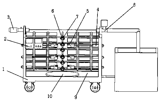
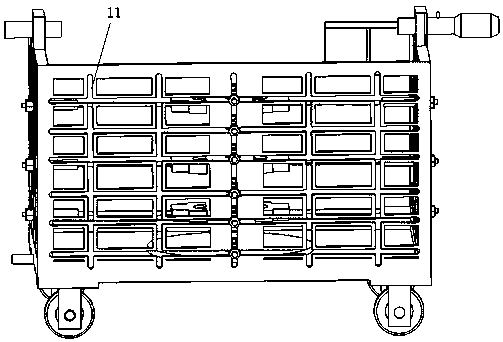
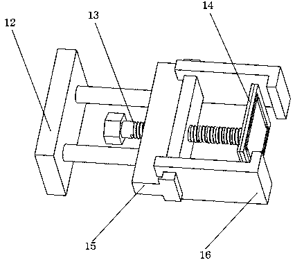
[0035]An energy-saving device for automatically detecting the airtightness of an exhaust manifold, comprising a detection vehicle 1, a starter and an alarm 2, and a water storage tank 21; three sides of the detection vehicle 1 are provided with a plurality of vertical and horizontal slides 11, and the vertical and horizontal The slideway 11 extends inwards a plurality of clamping devices 5 and a sealing device 7 with claws 16; the clamping devices 5 and sealing devices 7 are respectively connected to the power unit, and the tail of the power unit runs through the vertical and horizontal slideways 11 , moving on the vertical and horizontal slideway 11; the detection car 1 is provided with an automatic water injection pipe 8 and an automatic gas delivery pipe 3; the starter and the alarm 2 are arranged on the outside of the detection car, and are connected to the control system through sensors; The water storage tank 21 is arranged on the right side of the testing vehicle 1 and i...

Embodiment 2

[0039] The second embodiment is basically the same in structure and principle as the first embodiment, except that the clamping device 5 and the support base 10 are provided with electromagnetic coils inside. After placing the branch port of the exhaust manifold to be tested upright on the support base 10, the clamping device 5 and the electromagnetic coil inside the support base 10 are energized to form an electromagnet, which attracts the exhaust manifold to initially fix the exhaust manifold to be tested. exhaust manifold.

Embodiment 3

[0041] The third embodiment is basically the same in structure and principle as the first embodiment, except that the automatic gas delivery pipe 3 is provided with a high-power heating wire 19 and a pressure relief valve 20 inside. After completing the leak detection, open the pressure relief valve to release the pressure 20, discharge the water in the exhaust manifold, start the high-power heating wire 19, blow hot air into the exhaust manifold, and dry the residual moisture.


PUM


Abstract

The invention provides energy-saving equipment for automatic detection of air tightness of exhaust manifolds and a utilization method of the energy-saving equipment. The energy-saving equipment comprises a detection vehicle, a starter and alarm and a water storage pool. Three surfaces of the detection vehicle are provided with a plurality of longitudinal and transverse slide ways, and a pluralityof clamping devices and sealing devices with hook claws extend inwardly from the longitudinal and transverse slide ways. The clamping devices and the sealing devices are connected with power devices,and tails of the power devices penetrate the longitudinal and transverse slide ways and move on the longitudinal and transverse slide ways. The detection vehicle is provided with an automatic water injection pipe fitting and an automatic air delivery pipe fitting, and the starter and alarm is arranged on the outer side of the detection vehicle and connected with a control system through a sensor.The water storage pool is arranged on the right side of the detection vehicle and provided with a circulating water device connected with the detection vehicle. By means of high-pressure compression for detection of air tightness of the exhaust manifolds, the energy-saving equipment is direct and evident in detection effect and high in applicability and is provided with a water circulation systemto play a great role in energy saving.

Description

technical field [0001] The invention belongs to the technical field of auto parts, and relates to an energy-saving device and a use method for automatically detecting the airtightness of an exhaust manifold. Background technique [0002] The exhaust manifold is connected to the cylinder block of the automobile engine, and the exhaust gas discharged from each cylinder is collected and introduced into the exhaust main pipe, with a conduit with branch lines. At present, the common practice of various engine manufacturers is to package the three-way catalytic converter used to purify the exhaust gas in the exhaust manifold. If the airtightness of the exhaust manifold is not good, the exhaust gas will not only pollute the car body, but also reduce the exhaust gas of the vehicle. System life, more seriously, will cause pollution to the atmospheric environment. After the finished exhaust manifold is completed, it needs to pass the air tightness test. In the existing technology, th...

Claims


Application Information

Patent Timeline
Patent Type & Authority Patents(China)
IPC IPC(8): G01M3/28G01M3/04
Inventor 戚海冰
Owner LONGKOU VEHICLE VITTA
Why Eureka
Try Eureka