
Laser phase lock device and method

A phase-locking and laser technology, applied to lasers, laser components, phonon exciters, etc., can solve the problems of difficult optical path adjustment, lack of flexibility, and precise adjustment of optical devices

Pending Publication Date: 2018-01-19
SHANGHAI INST OF APPLIED PHYSICS - CHINESE ACAD OF SCI
View PDF10 Cites 10 Cited by
  • Summary
  • Abstract
  • Description
  • Claims
  • Application Information

AI Technical Summary

Problems solved by technology

[0006] The first is based on optical-microwave balanced phase detector, which is composed of Sagnac fiber ring, optical phase modulator driven by microwave signal, balanced optical detector and other optical devices. This technical scheme can realize ten Laser and microwave synchronization accuracy below femtosecond, but the phase detector is susceptible to the effect of optical pulse broadening and optical power imbalance. The former will increase the noise floor of the optical-microwave balanced phase detector, and the latter will cause the phase detector to work. The instability of the point, and the optical device that constitutes the optical-microwave balance phase detector needs to be fine-tuned, which is not flexible;
[0007] The second is based on the optical-optical phase detector, which is composed of multiple optical devices with BBO crystal or PPKTP crystal as the core, which can convert the coincidence degree of two beams of light pulses on the time axis into an electrical signal, so The phase detection accuracy of at least the optical pulse scale can be achieved, but the technical solution based on the optical-optical phase detector needs to lock the laser on an optical pulse reference signal first, and then extract the gigahertz microwave signal from the optical pulse reference signal. To indirectly realize the high-precision synchronization of the laser and the microwave. In addition, the optical-optical phase detector requires that the two beams of light pulses coincide on the time axis, so an additional electrical phase-locked loop is required. First, the two beams of light pulses are roughly phase-locked , and then adjust the phase of one beam of light pulses until the two beams of light pulses can overlap on the time axis, the technical solution is more complicated, and the optical path constituting the optical-optical phase detector is a free-space optical path, and the adjustment of the optical path is more difficult;

Method used


Image

  • Laser phase lock device and method
  • Laser phase lock device and method
  • Laser phase lock device and method

Examples


Embodiment Construction

[0050] The preferred embodiments of the present invention will be given below in conjunction with the drawings and described in detail.

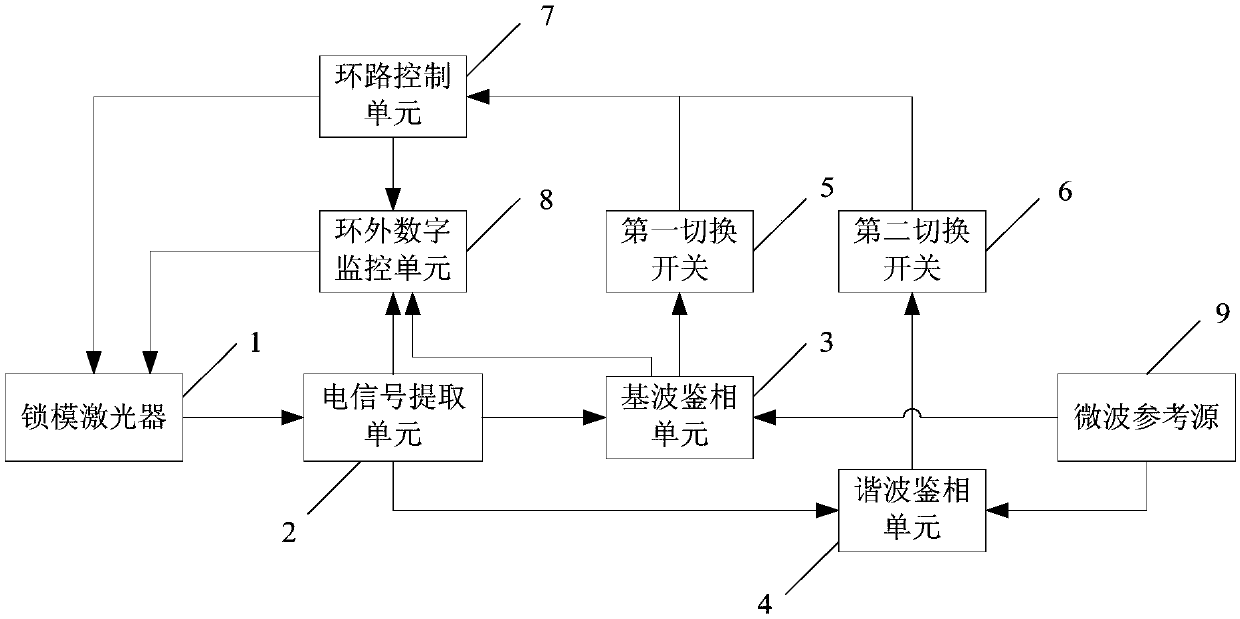
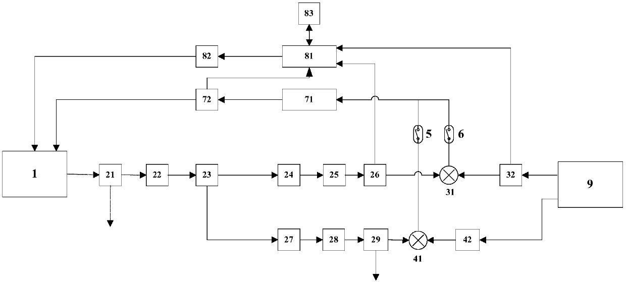
[0051] See attached Figure 1-4 One of the present invention is a laser phase-locking device, comprising: a mode-locked laser 1, an electrical signal extraction unit 2, a fundamental wave phase discriminating unit 3, a harmonic phase discriminating unit 4, a first switch 5, a second switch The switch 6, the loop control unit 7, the out-of-loop digital monitoring unit 8 and the external microwave reference source 9, wherein the first switch 5 and the second switch 6 are both analog switches.

[0052] The mode-locked laser 1 has a cavity mirror PZT (piezoelectric ceramic) control port and a cavity mirror motor control port.

[0053] The electric signal extraction unit 2 is connected to the mode-locked laser 1, and is used to convert the laser pulse train emitted by the mode-locked laser 1 into an electric signal, and extract the fundamental wave sig...


PUM


Abstract

The invention relates to a laser phase lock device and method. The device comprises a mode-locking laser device, an electric signal extraction unit, a microwave reference source, a foundamental wave phase discrimination unit, a harmonic wave phase discrimination unit, a first changeover switch, a second changeover switch, a loop control unit and an off-loop digital monitoring unit, wherein the mode-locking laser device and the electric signal extraction unit are sequentially connected, the foundamental wave phase discrimination unit and the harmonic wave phase discrimination unit are connectedwith the electric signal extraction unit and the microwave reference source, and the off-loop digital monitoring unit is connected between the loop control unit and the mode-locking laser device. Thedevice has a remarkable low-noise characteristic, the synchronous precision can reach the tens-of-femtosecond order, and the device also has high stability and is suitable for working occasions wherethe laser device needs to continuously run for a long time.

Description

Technical field [0001] The invention relates to a mode-locked laser phase-locking technology in the field of microwave photonics, in particular to a laser pulse train laser phase-locking device and method based on a dual microwave phase discriminator. Background technique [0002] Exploring and revealing the microstructure change process of matter at the atomic and molecular scale is of great significance to the development of many disciplines such as biology, chemistry, materials, environment, and medicine. To achieve this goal requires detection equipment with sub-nanometer spatial resolution. Rate and sub-femtosecond time resolution. Pump-probe user experiments based on X-ray light can observe atomic-scale microscopic phenomena with a time resolution of femtoseconds, so it has become a common detection method. [0003] At present, the time resolution of pump-probe user experiments based on X-ray light is mainly limited by the time jitter between the pump laser pulse and the X-r...

Claims


Application Information

Patent Timeline
IPC IPC(8): H01S3/098H01S3/10
Inventor 刘晓庆刘波张文艳
Owner SHANGHAI INST OF APPLIED PHYSICS - CHINESE ACAD OF SCI
Learn More