Self-propelled power transmission cable inspection robot
A technology for inspection robots and transmission lines, applied in overhead lines/cable equipment, two-dimensional position/channel control, etc., can solve problems such as poor monitoring reliability, achieve convenient real-time monitoring, high control stability, and improve reliability Effect
- Summary
- Abstract
- Description
- Claims
- Application Information
AI Technical Summary
Problems solved by technology
Method used
Image

Examples
Embodiment 1
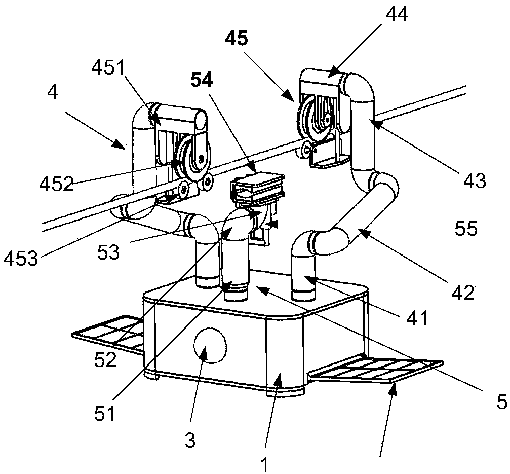
[0030] Such as figure 1 As shown, a self-propelled power transmission cable inspection robot, the robot includes a detection control box 1, a solar panel 2, a visual control system 3, two walking arms 4 and a clamping arm 5; the detection The side walls of the left and right ends of the control box 1 are respectively provided with solar panels 2; the visual control system 3 is arranged on the side walls of the front end and the rear end of the detection control box 1; It is rotatably installed on the left and right sides of the top surface of the detection control box 1. On the top surface of the detection control box 1, a clip is movably installed in a 360° rotatable manner at the position between the two walking arms 4. Hold arm 5; Described walking arm 4 comprises walking arm waist 41, walking arm shoulder 42, walking arm arm 43, walking arm wrist 44 and walking arm clamping part 45; The bottom of described walking arm waist 41 and The top surface of the detection control ...
Embodiment 2
[0034] The detection control box 1 is provided with a robot motion control system and a robot vision control system. Among them, such as Figure 9 As shown, the robot motion control system includes a device main controller 11, a clamping motor approaching a probe group 12, an ultrasonic ranging sensor group 13, a navigation positioning device 14, a remote wireless communication device 15, a mechanical arm sub-control device 16 and a solar energy The charging board sub-control device 17; the signal output end of the clamping motor approaching the probe group 12 is connected with the approaching probe detection signal input end of the device main controller; the ranging signal output end of the ultrasonic ranging sensor group 13 is connected with the device The ranging signal input end of the main controller 11 is connected; the positioning signal interactive end of the navigation and positioning device 14 is connected with the positioning signal interactive end of the device ma...
PUM
 Abstract
Description
Claims
Application Information
PatSnap Eureka turns technology decisions into work you can execute. Powered by our Innovation Knowledge Graph, it runs expert workflows across engineering, life sciences, materials and intellectual property. Get your review-ready output in minutes.


