Eureka AIR delivers breakthrough ideas for toughest innovation challenges, trusted by R&D personnel around the world.

Three-phase separating type hybrid power electronic transformer and control method thereof

A power electronics, three-phase separation technology, applied in AC network voltage adjustment, AC network to reduce harmonics/ripple, reactive power compensation and other directions, can solve the problems of power quality impact, lack of transformer, independent control and so on

Pending Publication Date: 2018-01-19
ELECTRIC POWER SCI RES INST OF GUIZHOU POWER GRID CO LTD
View PDF7 Cites 2 Cited by
  • Summary
  • Abstract
  • Description
  • Claims
  • Application Information

AI Technical Summary

Problems solved by technology

[0005] A three-phase separated hybrid power electronic transformer and its control method are provided to solve the problems that the traditional transformer does not have the ability to adjust the power quality of the power grid and the current power electronic transformer has a small capacity. The reactive power of each phase circuit cannot be dynamically independently compensated and independently controlled, and the current voltage compensation circuit brings more harmonics to the power grid, which has a greater impact on power quality.

Method used


Image

  • Three-phase separating type hybrid power electronic transformer and control method thereof
  • Three-phase separating type hybrid power electronic transformer and control method thereof
  • Three-phase separating type hybrid power electronic transformer and control method thereof

Examples


Embodiment Construction

[0042] Below in conjunction with accompanying drawing, the embodiment of the present invention is described in more detail:

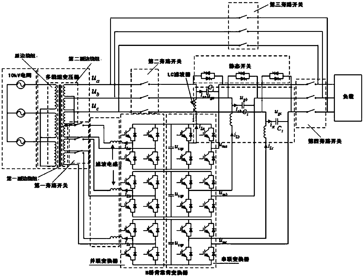
[0043] A three-phase separated hybrid power electronic transformer, including a multi-winding transformer and an H-bridge back-to-back converter, the multi-winding transformer includes a primary winding, a first secondary winding, and a second secondary winding, and the multi-winding transformer original The side winding is connected to the 10kV power grid in delta, the first secondary winding of the multi-winding transformer is connected to the first bypass switch, the first bypass switch, the filter inductor and the H-bridge back-to-back converter are connected in sequence, and the H-bridge back-to-back converter connected to the LC filter, the second secondary winding of the multi-winding transformer is respectively connected to the second bypass switch and the third bypass switch, the third bypass switch is connected to the load, and the second bypas...


PUM


Abstract

The invention discloses a three-phase separating type hybrid power electronic transformer and a control method thereof. The three-phase separating type hybrid power electronic transformer comprises amulti-winding transformer, an H-bridge back-to-back transformer and a static switch. According to the three-phase separating type hybrid power electronic transformer disclosed by the invention, quality regulation and control of electric energy can be realized, the capacity of a power electronic transformer can be effectively amplified, and high-power electric energy transmission can be realized; by adopting the three-phase separating type H-bridge back-to-back transformer, per-phase circuits adopt one single-phase full-bridge circuit, the per-phase circuits can be completely independent, reactive power independent compensation and independent control of each per-phase circuit and reactive current compensation and dynamic voltage recovery on split phases can be realized, and stability of output voltage can be ensured; meanwhile, effective switching of serial transformers can be realized through reasonable control on the static switch, the output voltage is enabled not to be influenced under normal operation, and the influence of harmonic waves generated by a compensation circuit to the electric energy quality can be effectively reduced.

Description

technical field [0001] The invention relates to the application field of power electronic devices in power systems, in particular to a three-phase separated hybrid power electronic transformer and a control method thereof. Background technique [0002] With the development and wide application of power electronic technology, power electronic transformers are attracting more and more attention. While the power electronic transformer has the advantages of small footprint, compact structure, and strong regulation ability, it also has the disadvantages of small capacity, low input and output voltage levels, and its power transmission capacity is much lower than that of traditional transformers. [0003] At present, the main function of the traditional transformer is to realize the transformation of the AC voltage level, realize the power transmission and distribution function of the power grid, and does not have the ability to adjust the power quality of the power grid, and the ...

Claims


Application Information

Patent Timeline
Patent Type & Authority Applications(China)
IPC IPC(8): H02J3/18H02J3/16H02J3/01
CPCY02E40/30Y02E40/40
Inventor 刘君马晓红张迅曾鹏陈沛龙杨涛曾华荣杨佳鹏许逵陈仕军刘宇田承越
Owner ELECTRIC POWER SCI RES INST OF GUIZHOU POWER GRID CO LTD
Why Eureka
Eureka Blog
Learn More