Drainage liquid monitoring management system

A technology of monitoring management and drainage fluid, which is applied in the field of external drainage, can solve the problems of inability to accurately analyze and judge the wound healing and drainage process, increase the workload of medical staff, and fail to understand the disease situation in time, so as to prevent delays in treatment and save manpower The effect of simple material and structure

Inactive Publication Date: 2018-01-26
PIONMEDEK MEDICAL TECH CO LTD
View PDF0 Cites 4 Cited by
  • Summary
  • Abstract
  • Description
  • Claims
  • Application Information

AI Technical Summary

Problems solved by technology

The current method mainly relies on medical personnel to observe with naked eyes or take regular samples for detection, which not only increases the workload of medical personnel, but also cannot monitor the drainage fluid in real time, resulting in the inability to understand the lesion in time, and unable to monitor the wound healing and drainage process. Precise Analysis and Judgment

Method used


Image

  • Drainage liquid monitoring management system
  • Drainage liquid monitoring management system
  • Drainage liquid monitoring management system

Examples


Embodiment 1

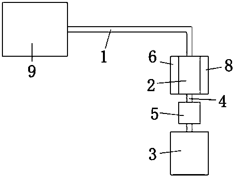
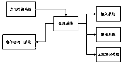
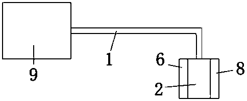
[0031] Such as figure 1 and figure 2 As shown, a drainage liquid monitoring and management system includes an external drainage tube 1 and a drop bottle 2, and the drainage tube is connected to the top of the drop bottle 2, wherein it also includes a processing system and a photoelectric detection system, and the photoelectric detection system A system is electrically connected to the processing system. The photoelectric detection system includes a light source 6 and a photoelectric sensing module 8 , and the light source 6 and the photoelectric sensing module 8 are oppositely arranged on both sides of the dropping bottle 2 . The light source 6 is a line light source 6 including the full band of visible light, and the photoelectric sensing module 8 is a linear array photoelectric sensing module 8 or an area array photoelectric sensing module 8 composed of 8 dot matrix photoelectric sensing modules. The response wavelength range of the photoelectric sensing module 8 should c...

Embodiment 2

[0039] This embodiment is similar to Embodiment 1, the difference is that, as image 3 As shown, the drainage fluid monitoring and management system also includes a liquid collection bag 3 and an electric drive valve system 5, the bottom end of the drop bottle 2 is connected to the liquid collection bag 3 through a conduit 4, and the electric drive valve system 5 is set on the conduit 4. Such as Figure 4 and Figure 5 As shown, the drop bottle 2 includes a drop bottle body 21 and a liquid collection communicator 7 arranged on one side of the drop bottle body 21, the inner chamber of the liquid collection communicator 7 is connected to the inner chamber of the drop bottle body 21. The cavity is connected, and the liquid level in the liquid collection connector 7 is always equal to the liquid level in the drop bottle body 21 and rises and falls synchronously; the light source 6 and the photoelectric sensor module 8 are relatively arranged in the liquid collection communicatio...


PUM


Abstract

The invention provides a drainage liquid monitoring management system which comprises an outer drainage pipe, a dropping bottle, a treatment system and a photoelectric detecting system. The drainage pipe is connected with the top end of the dropping bottle, the photoelectric detecting system is electrically connected with the treatment system, and the photoelectric detecting system comprises a light source and a photoelectric sensing module which are oppositely arranged on two sides of the dropping bottle. The light source is a line light source, the photoelectric sensing module is a linear array photoelectric sensing module or an area array photoelectric sensing module formed by dot array photoelectric sensing module parts, and a response wave band range of the photoelectric sensing module covers a wave band range of the light source. The drainage liquid monitoring management system can relieve the workload of medical staff and can simultaneously and timely monitor drainage liquid volume, accumulative drainage volume, drainage liquid color and turbidity.

Description

technical field [0001] The present invention relates to the technical field of external drainage, and more specifically, to a drainage fluid monitoring and management system. Background technique [0002] Drainage is a commonly used treatment method in the field of surgery, such as cerebrospinal fluid drainage, thoracic drainage, abdominal cavity drainage, etc. The purpose is to guide out the fluid or pus and blood accumulated between human tissues or in the body cavity, relieve local pressure, and prevent the accumulation of fluid from affecting adjacent organs. Compression and tissue damage, prevent postoperative infection and promote wound healing. [0003] During the drainage process, the amount of body fluid drainage is an important content for clinical medical staff to observe the condition. Usually, the volume of the drained body fluid is used as the recording basis. The amount of body fluid drainage can be used as one of the important indicators for judging the chang...

Claims


Application Information

Patent Timeline
Patent Type & Authority Applications(China)
IPC IPC(8): A61M1/00A61B5/1455A61B5/00
Inventor 陈慕奇文平
Owner PIONMEDEK MEDICAL TECH CO LTD
Why Eureka
Try Eureka