Luneberg lens design method based on 3D printing technology

A Longbo lens and 3D printing technology, applied in computing, antenna, application and other directions, can solve the problems of lengthy production process and high production cost, achieve broad market prospects, high printing accuracy, and ensure product performance.

Active Publication Date: 2018-01-26
BEIJING AEROSPACE INST OF THE LONG MARCH VEHICLE +1
View PDF3 Cites 18 Cited by
  • Summary
  • Abstract
  • Description
  • Claims
  • Application Information

AI Technical Summary

Problems solved by technology

However, the existing technology is limited by factors such as material matching, material parameter precision

Method used


Image

  • Luneberg lens design method based on 3D printing technology
  • Luneberg lens design method based on 3D printing technology
  • Luneberg lens design method based on 3D printing technology

Examples


Embodiment Construction

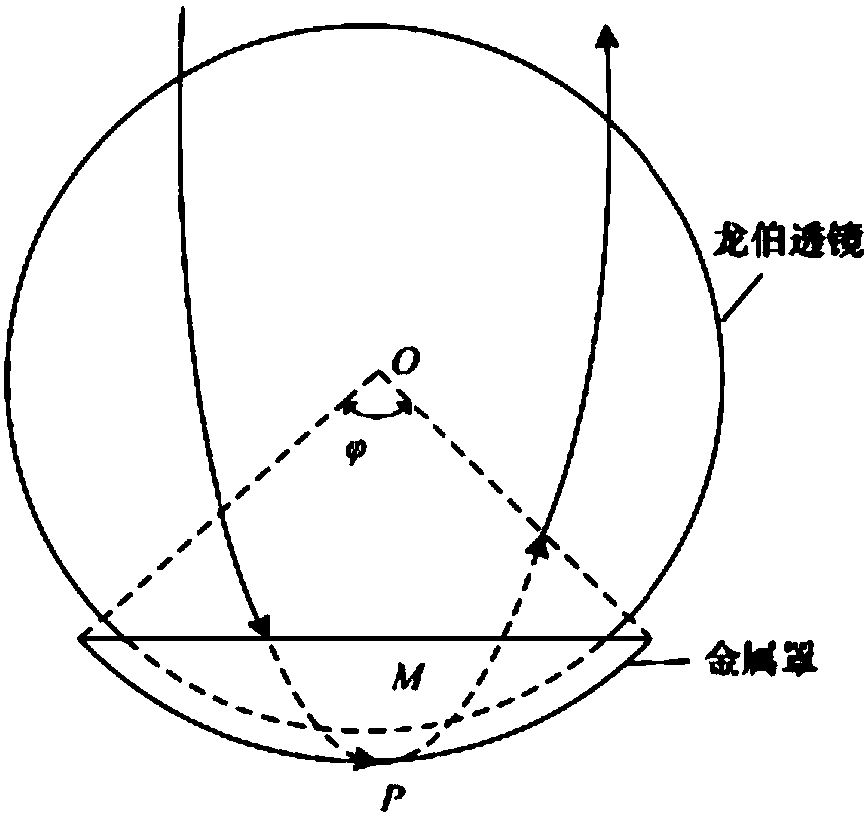
[0038] The present invention overcomes the deficiencies of the prior art, and provides a design method for Lunberg lenses based on 3D printing technology, which can realize rapid design and rapid prototyping of Lunberg scatterers with specific frequency points and specific RCS indicators compared with the prior art , which effectively improves the design level of electromagnetic target characteristics and the level of process realization, and has good practical value. The method of the present invention will be described in detail below in conjunction with the accompanying drawings.

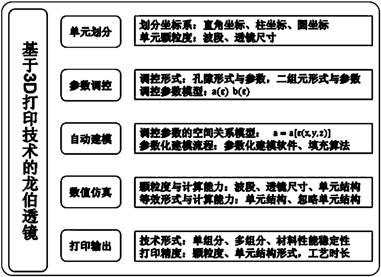
[0039] The invention does not require mechanical processing and moulds, and directly generates parts of any shape required from computer graphics data. The cost is 1 / 4 of the traditional layered structure, and the processing time is only a few hours. The rapid realization of specified RCS parameters can be completed. The specific scheme is as follows, the whole Lunberg lens is divided into several...


PUM


Abstract

The invention relates to a Luneberg lens design method based on a 3D printing technology. Firstly, m kinds of 3D printing materials are selected, and the Luneberg lens unit type and the Luneberg lensunit size are determined; according to the Luneberg lens effective dielectric constant, the unit type and the unit size, void contents of all points of Luneberg lens units are determined; according tothe obtained unit type, the obtained unit size and the obtain void contents of all points of the Luneberg lens units, corresponding Luneberg lens 3D models are built, and whether the Luneberg lens 3Dmodels meet spherical radial graded refractive index profile or not is verified; and finally, the Luneberg lens 3D models meeting the spherical radial graded refractive index profile are printed, anda Luneberg lens is generated. Compared with an existing technology, the method achieves quick molding of the Luneberg lens through the 3D printing technology, and has the beneficial effects that theprinting accuracy is high, each printing element dielectric constant can be controlled singly, the true graded refractive index is achieved, and the product performance is guaranteed.

Description

technical field [0001] The invention relates to a Lumberg lens design method based on 3D printing technology. Background technique [0002] Luneberg lens is a dielectric lens with a spherical shape, which can gather and capture electromagnetic waves in any direction, so that incident plane waves can converge at one point. By installing a metal reflector on the surface of the sphere, the concentrated electromagnetic wave is reflected along a path symmetrical to the incident path, and a counterpropagating plane wave is formed again, forming an efficient RCS enhanced reflector, such as figure 1 Shown is a schematic diagram of Lunberg lens principle. In addition, based on its electromagnetic beam focusing ability, Lunberg lens is also used to realize low-cost, high-gain microwave lens antenna. [0003] The core characteristic of the Lunberg lens is that the refractive index along the radial direction of the sphere obeys the following law of gradual distribution: n=[2-(r / R)2]1 / ...

Claims


Application Information

Patent Timeline
IPC IPC(8): B29C64/386B33Y50/00G06F17/50B29L11/00
CPCH01Q15/02
Inventor 束逸张力李志峰李建华刘佳琪刘鑫刘洪艳高路赵巨岩杜润乐薛莲薛峰赵茜蔡雯琳
Owner BEIJING AEROSPACE INST OF THE LONG MARCH VEHICLE
Why Eureka
Try Eureka