
Movable garbage waste gas treatment device

A waste gas treatment device and garbage technology, which is applied in the direction of combined devices, lighting and heating equipment, and separation of dispersed particles, can solve the problems of irritating odor, high investment cost, and large fuel consumption, with obvious effects and low construction cost , Increase the effect of using time

Active Publication Date: 2018-01-26
上海启菲特环保生物技术有限公司
View PDF4 Cites 3 Cited by
  • Summary
  • Abstract
  • Description
  • Claims
  • Application Information

AI Technical Summary

Problems solved by technology

[0002] With the development of the economy, people pay more and more attention to the surrounding environment; it is known that the waste gas contains a large amount of harmful bacteria, viruses and organic gases, and these substances emit a foul smell, which is an important cause of air pollution, especially the garbage disposal station The exhaust gas has a pungent smell; in order to protect and improve the sanitation quality of various processing sites and surrounding environments, reduce secondary pollution to the air, and effectively control the stench; generally use drugs to disinfect and burn garbage, but this is easy The highly toxic gas produced cannot be degraded, causing secondary pollution, and burning requires a large amount of fuel, high input costs, and difficult management; and the waste gas after the reaction is absorbed by the cleaning solution, which will also cause secondary pollution

Method used

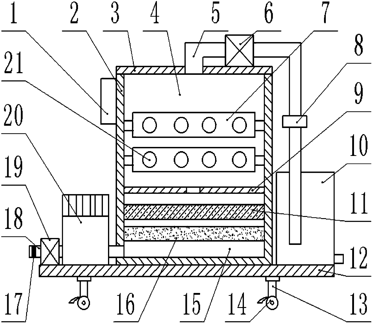

Image

  • Movable garbage waste gas treatment device
  • Movable garbage waste gas treatment device
  • Movable garbage waste gas treatment device

Examples


Embodiment Construction

[0016] The technical solution of this patent will be further described in detail below in conjunction with specific embodiments.

[0017] Embodiments of the present patent are described in detail below, examples of which are shown in the drawings, wherein the same or similar reference numerals designate the same or similar elements or elements having the same or similar functions throughout. The embodiments described below by referring to the figures are exemplary and are only used for explaining the patent, and should not be construed as limiting the patent.

[0018] In the description of this patent, it is to be understood that the terms "center", "upper", "lower", "front", "rear", "left", "right", "vertical", "horizontal", The orientation or positional relationship indicated by "top", "bottom", "inner", "outer", etc. is based on the orientation or positional relationship shown in the drawings, and is only for the convenience of describing this patent and simplifying the des...


PUM


Abstract

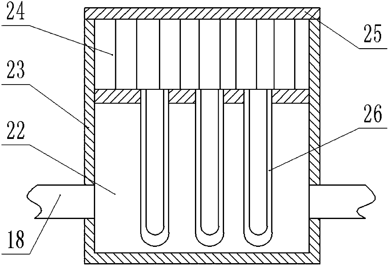
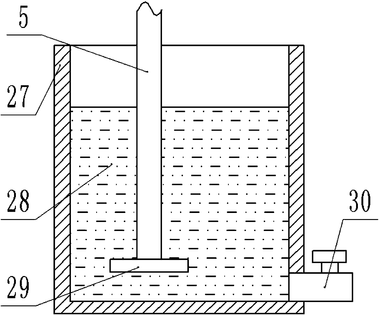
The invention provides a movable garbage waste gas treatment device, and belongs to the field of waste gas treatment device. The movable garbage waste gas treatment device comprises a shell, an absorption device and a cooling device. The shell is arranged to be a cuboid and is put vertically, and a reaction cavity and a filter cavity are formed in the shell. A partition plate is arranged between the reaction cavity and the filter cavity, and the reaction cavity is formed in the upper end. A base in fixed connection is arranged at the lower end of the shell, and an upper end cover in threaded connection is arranged at the upper end of the shell. An exhaust pipe is arranged in the middle of the upper end cover. The left end of the exhaust pipe penetrates the upper end cover to be connected with the reaction cavity, and the connected absorption device is arranged at the right end of the exhaust pipe. The exhaust pipe is further provided with a second air extractor and a stop valve. The second air extractor is arranged at the left end and is fixedly connected to the upper surface of the upper end cover. Two ultraviolet lamp panels are arranged below, and the left end and the right endof each ultraviolet lamp panel are fixedly connected to the inner surface of the shell. The movable garbage waste gas treatment device has the beneficial effects of being simple in structure, convenient to use, convenient to manage and maintain, low in building cost, remarkable in waste gas treatment effect and the like.

Description

technical field [0001] The invention relates to a waste gas treatment device, in particular to a mobile garbage waste gas treatment device. Background technique [0002] With the development of the economy, people pay more and more attention to the surrounding environment; it is known that the waste gas contains a large amount of harmful bacteria, viruses and organic gases, and these substances emit a foul smell, which is an important cause of air pollution, especially the garbage disposal station The exhaust gas has a pungent smell; in order to protect and improve the sanitation quality of various processing sites and surrounding environments, reduce secondary pollution to the air, and effectively control the stench; generally use drugs to disinfect and burn garbage, but this is easy The highly toxic gas produced cannot be degraded, causing secondary pollution, and the combustion requires a large amount of fuel, high input costs, and difficult management. In addition, the w...

Claims


Application Information

Patent Timeline
Patent Type & Authority Applications(China)
IPC IPC(8): F23J15/04F23J15/00B01D50/00B01D53/04B01D53/18B01D53/00
Inventor 李盼君
Owner 上海启菲特环保生物技术有限公司
Learn More