External combined heat pipe

An external heat pipe technology, applied in the direction of indirect heat exchangers, lighting and heating equipment, etc., can solve the problems of heat exchanger installation, transportation impact, heat exchanger hot water storage decline, large metal pipe size, etc., to achieve reduction Small size and installation weight, increased heat transfer efficiency, light weight effect

Pending Publication Date: 2018-01-26
ZHEJIANG JINSITONG TECH CO LTD
View PDF3 Cites 0 Cited by
  • Summary
  • Abstract
  • Description
  • Claims
  • Application Information

AI Technical Summary

Problems solved by technology

Due to the presence of fins and the large size and heavy weight of the metal tubes used, the size and weight of the heat exchanger are too large and heavy
As a result, more space needs to be arranged in the entire steam generation system to place the heat exchanger, resulting in a decrease in the hot water storage capacity of the heat exchanger
On the other hand, the weight of the heat exchanger also has a great impact on the overall installation and transportation.

Method used


Image

  • External combined heat pipe
  • External combined heat pipe

Examples


Embodiment 1

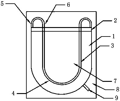
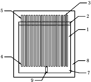
[0019] Such as Figures 1 to 2 As shown, an external combined heat pipe includes a U-shaped housing 1, a bracket 2 fixedly connected to the opening of the U-shaped housing 1, and a plurality of miniature microchannel metal heat dissipation round tubes 3. The miniature microchannels The metal heat dissipation circular tube 3 includes a condensation section 4, an adiabatic section 5, and an evaporation section 6, and it is characterized in that the support 2 is used to fixedly support the condensation section 4 of the plurality of miniature microchannel metal heat dissipation circular pipes 3, so The inner diameter of the miniature micro-channel metal heat dissipation circular tube 3 is 0.05-0.6mm, the wall thickness is 0.15-0.25mm, and the outer diameter is less than 0.9mm; there is a closed space 7 between the U-shaped housing 1 and the bracket 2; The thermal insulation section 5 and the evaporation section 6 of the miniature microchannel metal heat dissipation circular tube 3...


PUM


Abstract

The invention discloses an external combined heat pipe. The external combined heat pipe comprises a U-shaped shell, a support and a plurality of miniature micro-channel metal heat dissipation circularpipe bodies, wherein the support is fixedly connected to an opening of the U-shaped shell; each miniature micro-channel metal heat dissipation circular pipe body comprise a condensation section, a heat insulation section and an evaporation section; the support is used for fixing and supporting the condensation sections of the miniature micro-channel metal heat dissipation circular pipe bodies; the inner diameter of each miniature micro-channel metal heat dissipation circular pipe body is 0.05-0.6mm, the wall thickness is 0.15-0.25mm, and the outer diameter is below 0.9mm; a closed space is formed between the U-shaped shell and the support; the heat insulation sections and the evaporation sections of the miniature micro-channel metal heat dissipation circular pipe bodies are arranged outside the closed space; and the tail ends of the evaporation sections penetrate through the U-shaped shell to extend into the closed space and are close to the bottom of the u-shaped shell.

Description

technical field [0001] The invention designs a micro-microchannel heat exchange technology, in particular an external combined heat pipe. Background technique [0002] Low-temperature waste heat is waste heat below 350°C, and the quantity is extremely large, including hot water, low-grade flue gas and steam generated in the production process of metallurgy, building materials, petrochemical and other industries. At present, low-temperature waste heat is mainly used in heating, hot water and other fields. At present, domestic and civil low-temperature waste heat steam generation systems are rare, and there are only some extruded aluminum alloy metal tubes or flat tubes with fins, and the inner hole size of the tubes is greater than 0.6mm. And compared with the traditional tube-fin type, tube-belt type, parallel flow type, plate-fin type, stacked type and other heat exchangers, the heat exchange efficiency is not particularly significantly improved. Due to the presence of fi...

Claims


Application Information

Patent Timeline
Patent Type & Authority Applications(China)
IPC IPC(8): F28D15/02
Inventor 臧东云
Owner ZHEJIANG JINSITONG TECH CO LTD
Why Eureka
Try Eureka