Ventricular wall injection assist device

A technology of ventricles and instruments, applied in the field of ventricular wall injection auxiliary instruments, can solve the problems of affecting the marking accuracy, increasing the difficulty of operation, disappearing, etc., and achieve the effects of avoiding pigment pollution, saving operation time, and improving positioning accuracy

Active Publication Date: 2022-06-24
DEKE MEDTECH HANGZHOU INC
View PDF12 Cites 0 Cited by
  • Summary
  • Abstract
  • Description
  • Claims
  • Application Information

AI Technical Summary

Problems solved by technology

During the operation, in order to minimize the harm to the patient, it is necessary to strictly control the size of the thoracotomy incision, and perform operations such as marking and injection in as small an incision as possible. Since the exposed chest space is very narrow, the doctor draws and During the process of marking the injection point, the field of vision is limited, and it is often only operated with one hand, which is difficult; and during the whole operation, the heart is always beating, and the doctor uses a marking pen to draw marking lines and positioning points on the surface of the heart It is more difficult, and it will greatly prolong the operation time and increase the risk of the patient; and because the heart is exposed to the air for a long time, the trauma to the patient will be relatively large
At the same time, the pigment used in the logo will also diffuse or even fall off during the beating process of the heart, resulting in the blurring or even disappearance of the injection point of the mark, requiring repeated repainting, which further increases the difficulty of operation and affects the accuracy of the mark
In addition, the marking pigment remains in the patient's body after falling off, and cannot be completely excreted with the patient's metabolism, causing pollution in the body, which will increase the biological risk
[0005] In summary, the existing ventricular wall injection methods have problems such as long operation time, inconvenient marking of injection points, inaccurate positioning of injection points, and contamination of marking pigments.

Method used


Image

  • Ventricular wall injection assist device
  • Ventricular wall injection assist device
  • Ventricular wall injection assist device

Examples


Embodiment 1

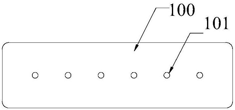
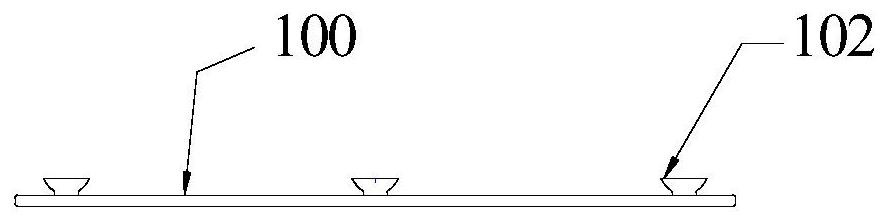
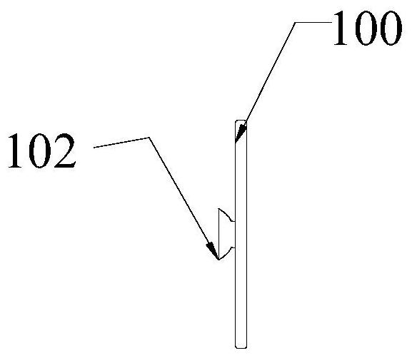
[0034] see Figure 1a to Figure 1c , the ventricular wall injection auxiliary device of this embodiment includes a flexible band-shaped main body 100 . The belt-shaped body 100 is made of a biocompatible material, and a plurality of positioning holes 101 are distributed on the belt-shaped body 100 . A plurality of vacuum suction cups 102 are disposed on the back of the belt-shaped body 100 , and the positions of the vacuum suction cups 102 and the positioning holes 101 do not overlap. During the operation, the operator can place the strip body 100 on the surface of the patient's heart, connect the strip body 100 to the heart surface through the vacuum suction cup 102 , and then inject hydrogel into different regions of the ventricular wall through the positioning hole 101 respectively. A non-contractile substance that increases the thickness of the ventricular wall, reduces the tension of myocardial fibers, improves cardiac function, and delays or treats the progression of hea...

Embodiment 2

[0052] see Figure 3a and Figure 3b The structure of the ventricular wall injection auxiliary device in the second embodiment is basically the same as that of the ventricular wall injection auxiliary device in the first embodiment. The difference is that in the ventricular wall injection auxiliary device in the second embodiment, the four vacuum suction cups 10 are distributed in The four corners of the strip body 100 . see Figure 4a and Figure 4b , In this embodiment, the vacuum suction cup 102 is a pneumatic suction cup, and the proximal opening of the pneumatic suction cup can be connected with a negative pressure device.

[0053] The use process of the ventricular wall injection auxiliary device of this embodiment is as follows:

[0054] Step 1: After opening the chest to expose the heart, confirm that the middle level of the left ventricle is the injection site, attach the strip body 100 of the ventricular wall injection aid to the injection site in the middle of t...

Embodiment 3

[0059] see Figure 5 The structure of the auxiliary device for ventricular wall injection in the third embodiment is basically the same as that of the auxiliary device for ventricular wall injection in the first embodiment. Two rows of positioning holes 101 . The lateral distance between the two rows of positioning holes 101 is in the range of 12-20 mm, and the longitudinal distance between two adjacent positioning holes 101 in each row is in the range of 12-18 mm. In this embodiment, the lateral distance between the two rows of positioning holes 101 is 16 mm, and the longitudinal distance between two adjacent positioning holes 101 in each row is 15 mm. The number of positioning holes 101 in each row is six. Among the two rows of positioning holes, the six upper row positioning holes 101 and the six lower row positioning holes 101 are respectively provided in a one-to-one correspondence. Corresponding arrangement means that the connection line between the upper row of posit...


PUM


Abstract

The invention discloses a ventricular wall injection assisting device, which comprises a flexible belt-shaped main body made of biocompatible materials, a plurality of positioning holes are distributed on the belt-shaped main body, and the belt-shaped main body is made of biocompatible materials. A plurality of vacuum suction cups are arranged on the back of the main body, and the positions of the vacuum suction cups and the positioning holes do not coincide. In the ventricular wall injection assisting device of the present invention, a detachable connection is formed between the vacuum suction cup and the outer surface of the heart to fix the belt-shaped main body on the outer surface of the heart. Injecting non-contracting substances such as hydrogels separately can effectively improve the positioning accuracy of the injection point, shorten the operation time, and avoid residual pigment pollution in the patient's body.

Description

technical field [0001] The invention relates to the field of medical devices, in particular to an auxiliary device for ventricular wall injection. Background technique [0002] Heart failure, referred to as heart failure, refers to the failure of the systolic and / or diastolic function of the heart to fully discharge the venous blood back to the heart, resulting in blood stasis in the venous system and insufficient blood perfusion in the arterial system, resulting in cardiac circulatory disorder syndrome. Existing treatment methods, such as traditional drug therapy, assistive devices and heart transplantation, all face many difficulties. For example, many patients have recurrent symptoms after traditional drug therapy, cardiac resynchronization therapy is not suitable for all patients, and some patients have poor response. The source of donors for heart transplantation is very limited. [0003] Implantable hydrogel is a new type of heart failure treatment technology. Specifi...

Claims


Application Information

Patent Timeline
Patent Type & Authority Patents(China)
IPC IPC(8): A61M5/42
Inventor 张庭超李阳刘格源
Owner DEKE MEDTECH HANGZHOU INC
Why Eureka
Try Eureka