
Optimization design method of blunt trailing edge airfoil under condition of surface roughness of wind turbine blade

A technology for wind turbine blades and rough surface is applied in the field of airfoil optimization design and modification to achieve the effects of improving aerodynamic performance, improving wind energy utilization, and improving accuracy

Inactive Publication Date: 2018-01-30
TIANJIN POLYTECHNIC UNIV
View PDF0 Cites 14 Cited by
  • Summary
  • Abstract
  • Description
  • Claims
  • Application Information

AI Technical Summary

Problems solved by technology

[0005] Although researchers have done a lot of research on the optimal design of the airfoil and the modification of the blunt trailing edge over the years, and both the optimized design and the modification of the blunt trailing edge can improve the aerodynamic performance of the airfoil with rough surface, but the airfoil with the blunt trailing edge The influence of the blunt trailing edge thickness and its distribution ratio on the upper and upper sides of the mid-arc in the parameterized expression of the line and the research on the optimal design have not involved

Method used


Image

  • Optimization design method of blunt trailing edge airfoil under condition of surface roughness of wind turbine blade
  • Optimization design method of blunt trailing edge airfoil under condition of surface roughness of wind turbine blade
  • Optimization design method of blunt trailing edge airfoil under condition of surface roughness of wind turbine blade

Examples


Embodiment

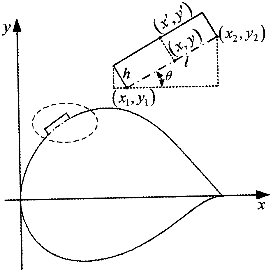
[0086] 1. The S822 airfoil is widely used in the main power generation area of ​​wind turbine blades, with a maximum relative thickness of 16% at 39.2%c, and a maximum relative camber of 1.92% at 59.5%c; on the upper surface of the airfoil 2%c Add a boss with height h=0.003c and width l=3mm.

[0087] 2. Optimizing the initial conditions is: take the Reynolds number Re as 5×10 5 , the Mach number Ma is 0.11, the population size is 20, the maximum evolutionary generation is 300 generations, and the learning factor S 1 , S 2 is 0.5, and the variable dimension is 20; in order to make the algorithm program have both strong search ability and good convergence, the inertia weight w adopts the linear reduction adaptive adjustment formula:

[0088]

[0089] In the formula, w max and w min Indicates the maximum and minimum values ​​of inertia weight, 0.9 and 0.4 are selected according to design experience; t and t max Indicates the current and maximum evolutionary generations.

...


PUM


Abstract

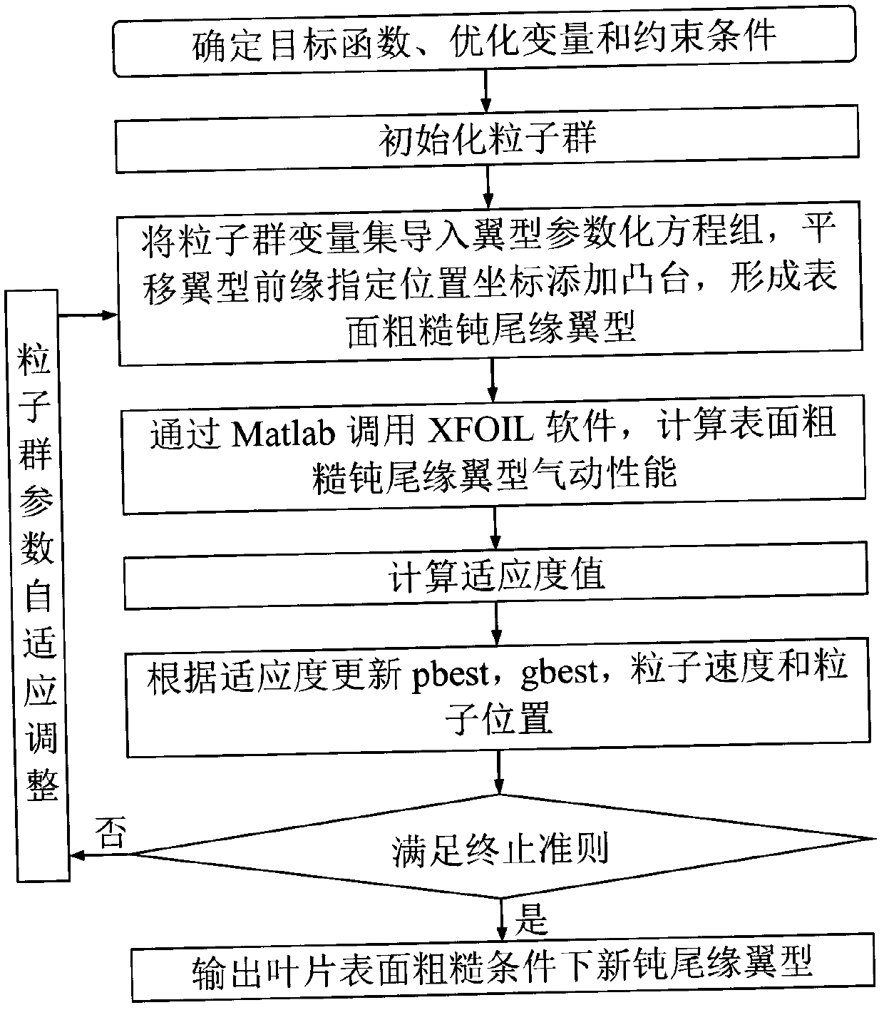
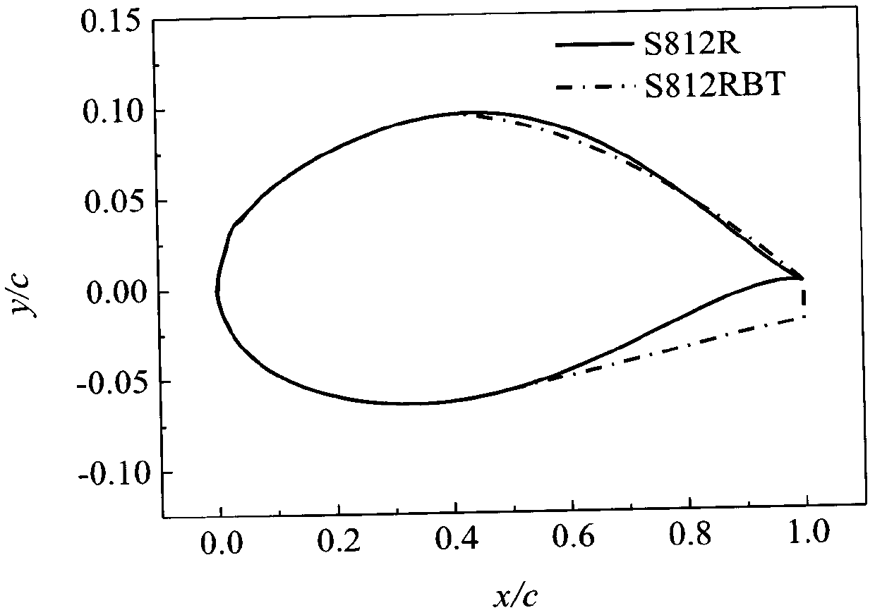
The present invention discloses an optimization design method of a blunt trailing edge airfoil under the condition of surface roughness of a wind turbine blade. The method comprises the following steps: forming parameterized control equations of a blunt trailing edge airfoil profile by adopting a generalized functional integrated expression and a B-spline curve of the wind airfoil; by using the method of shifting coordinates of the specified position of the leading edge of the airfoil, adding a boss to the specified position of the suction surface to simulate the surface roughness of the blade; taking a shape function coefficient of the airfoil, control parameters of the B-spline curve, the thickness of the blunt trailing edge and a distribution ratio of the blunt trailing edge on the upper side of the mean camber line as design variables, using particle swarm optimization coupled XFOIL software to optimize the rough blunt trailing edge airfoil profile, and proposing an optimization design method of the blunt trailing edge airfoil under the condition of the surface roughness of the blade; and for the rough S822R airfoil (R represents rough), optimizing to obtain the blunt trailingedge modification with thickness of 2.13% and thickness distribution ratio of 0:1, and using the CFD method to study the lift and drag coefficients and the ratio of lift to drag of the airfoil. According to the method disclosed by the present invention, the aerodynamic performance of the blunt trailing edge airfoil under the condition of the surface roughness of the wind turbine blade can be significantly improved, and the wind energy utilization efficiency of the wind turbine under the harsh working environment is better enhanced.

Description

technical field [0001] The invention belongs to the technical field of airfoil optimization design and modification, and in particular relates to an optimization design method of blunt trailing edge airfoil under the condition of rough surface of wind turbine blade by using computational fluid dynamics and optimization algorithm. Background technique [0002] Wind turbines mostly work in areas with harsh environments such as alpine, coastal, and frequent sandstorms, and the surfaces of their blades often adhere to dirt such as dust, insects, rain and snow. Fouling increases the roughness of the blade surface and significantly reduces the annual energy production of wind turbines. Designing an airfoil with low sensitivity to roughness is an effective solution to reduce or eliminate the influence of attached dirt on the aerodynamic performance of the airfoil, thereby ensuring the efficient operation of the wind turbine under rough blade surface conditions. [0003] The direct...

Claims


Application Information

Patent Timeline
IPC IPC(8): G06F17/50
Inventor 张旭苏万清李伟王格格刘海龙
Owner TIANJIN POLYTECHNIC UNIV
Learn More