Super-deep diaphragm wall rigid connector comprehensive water stop system and construction method thereof

A technology of rigid joint and ground connection wall, which is applied in sheet pile wall, foundation structure engineering, construction, etc., can solve the problems of uneven settlement of surrounding ground, easy generation of quicksand, and unsmooth grouting, and achieves good application effect and technology. The effect of fewer links, lower requirements and lower construction costs

Pending Publication Date: 2018-02-02
CHINA CONSTR FIRST DIV GROUP CONSTR & DEV
View PDF8 Cites 5 Cited by
  • Summary
  • Abstract
  • Description
  • Claims
  • Application Information

AI Technical Summary

Problems solved by technology

[0003] The purpose of the present invention is to provide an ultra-deep ground wall rigid joint comprehensive water-stop system and its construction method, to solve the technical problems of quicksand, piping, and uneven settlement of the surrounding ground in the prior art; and to solve the complex construction of the prior art, And the problem of grouting is not smooth

Method used


Image

  • Super-deep diaphragm wall rigid connector comprehensive water stop system and construction method thereof
  • Super-deep diaphragm wall rigid connector comprehensive water stop system and construction method thereof

Examples


specific Embodiment

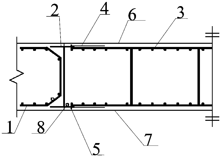
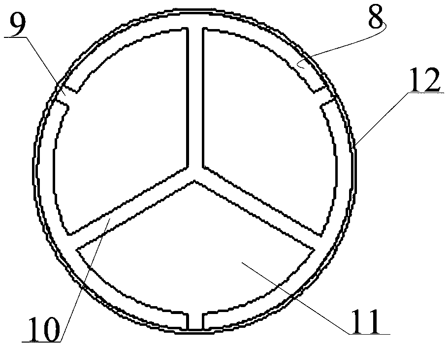
[0039]In this embodiment, the width of the flange of the I-beam joint is 350mm, and its bottom end is 500mm deeper than the bottom of the ground connection wall groove; the width of the grout-stop iron sheet is 500mm, and the thickness is 0.35mm; For the grouting pipe, the top of the pipe is 300mm higher than the top of the ground connection wall; the diameter of the grouting hole is 4mm, the distance below the groundwater level is 500mm, and the hole is wrapped with 2 layers of grout-stop tape with a width of 80mm. For the medium-fine sand mixed soil layer and the ultra-deep ground connection wall, micro-expansion ultra-fine cement slurry is used, the water-cement ratio is 0.7~0.8, and the grouting pressure is 0.4~1MPa. Compared with the joint water-stopping system of the ultra-deep ground-wall rigid joints or ordinary rigid joints combined with high-pressure rotary grouting piles, the construction cost of the ultra-deep ground-wall rigid joint comprehensive water-stop system ...


PUM


Abstract

The invention discloses a super-deep diaphragm wall rigid connector comprehensive water stop system and a construction method thereof. The super-deep diaphragm wall rigid connector comprehensive waterstop system is arranged between a pit facing face and a soil facing face and comprises a first-stage groove section reinforcement cage, an I steel connector and a second-stage groove section reinforcement cage, wherein the first-stage groove section reinforcement cage, the I steel connector and the second-stage groove section reinforcement cage are sequentially arranged from left to right. The connector end of the first-stage groove section reinforcement cage is provided with a head sealing rib. The second-stage groove section reinforcement cage is fixedly connected with the inner side of anI steel connector flange slab, and grout stop iron sheets and pressure welding ribs are arranged on the outer sides of connecting joints of the second-stage groove section reinforcement cage and the Isteel connector flange slab. A multi-time grouting pipe is arranged at the position, close to the corner portion of the soil facing face, of the connecting end of the first-stage groove section reinforcement cage and the second-stage groove section reinforcement cage, the bottom of the multi-time grouting pipe is sealed, and the outer wall of the multi-time grouting pipe is wrapped by grouting adhesive tape. Partition blades are arranged in the multi-time grouting pipe and separate the multi-time grouting pipe into three one-time grouting channels, and the outer wall of each one-time groutingchannel is provided with a row of grout jetting holes which are evenly arranged along the multi-time grouting pipe at intervals. The super-deep diaphragm wall rigid connector comprehensive water stopsystem and the construction method thereof have the beneficial effects of being safe, applicable and the like, very good popularization and practical value is achieved, and good economic benefits canbe generated after wide application and popularization.

Description

technical field [0001] The invention belongs to the field of construction engineering, and relates to a ground-wall joint water-stop system, in particular to an ultra-deep ground-wall rigid joint comprehensive water-stop system and a construction method thereof. Background technique [0002] In recent years, the application of the ground-wall support system in various super-large and deep foundation pit projects has been rapidly developed. It has the characteristics of high rigidity, good anti-seepage performance, and low construction noise. In super large and deep complex foundation pits with high height and deep foundation pit. However, due to various complex conditions during the construction process, quality problems such as mud inclusions and slag inclusions are likely to occur at the joints of the conventional flexible joints in the ground connection wall groove section, resulting in local leakage during excavation of the foundation pit, and even quicksand, piping, and...

Claims


Application Information

Patent Timeline
Patent Type & Authority Applications(China)
IPC IPC(8): E02D5/18
CPCE02D5/185
Inventor 周予启任耀辉林春平杨亮黄勇魏健聂艳侠范围单仁禹李双全
Owner CHINA CONSTR FIRST DIV GROUP CONSTR & DEV
Why Eureka
Try Eureka