
Quantum cryptography implementation method based on quantum light source

A technology of quantum cryptography and implementation method, applied in the application field, can solve the problems of low coincidence rate, unreachable signal state of optimal strength, poor performance, etc., and achieve the effect of eliminating intensity modulation error, excellent practical performance and huge development potential.

Active Publication Date: 2018-02-02
NANJING UNIV OF POSTS & TELECOMM
View PDF7 Cites 11 Cited by
  • Summary
  • Abstract
  • Description
  • Claims
  • Application Information

AI Technical Summary

Problems solved by technology

However, in the actual quantum cryptography scheme, due to some defects in the previous protocols and systems based on quantum light sources, the actual performance is poor, so most of the QKD systems use WCS
[0004] In the conventional scheme of generating HSPS, SAPD (Silicon Avalanche Photo-Diode, silicon avalanche diode) is commonly used as a single photon detector for local detection, and the saturation threshold of the detector will limit the intensity of pump power and signal light, so the optimal strength of the signal state cannot be reached
In addition, using the current technology, due to the unsatisfactory coupling efficiency and detection efficiency, the photon pairs generated by the PDC process have a low coincidence rate, resulting in a low marking efficiency of HSPS, which obviously reduces the key extraction using the HSPS protocol. Rate
Moreover, in the QKD system using phase encoding, the signal light needs to pass through the Mach-Zehnder (MZ) or Faraday-Michslson interferometer, which usually has a large system loss, especially when using a quantum light source.
Therefore, there are few QKD experiments based on quantum light sources so far, and most of them have poor performance compared with WCS

Method used


Image

  • Quantum cryptography implementation method based on quantum light source
  • Quantum cryptography implementation method based on quantum light source
  • Quantum cryptography implementation method based on quantum light source

Examples


Embodiment 1

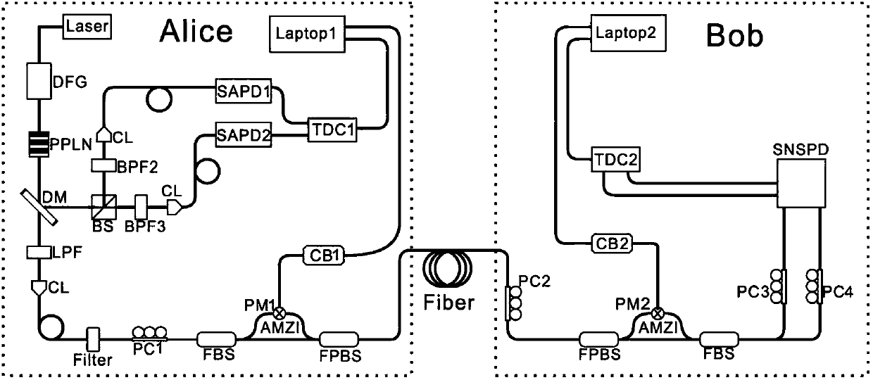
[0020] In the scheme of the present invention, a decoy state method and a novel low-loss unequal-arm MZ interferometer are adopted.

[0021] In the QKD system conventionally using HSPS light sources of the present invention, the dual-mode light field state obtained from the parametric down-conversion process can be described as:

[0022]

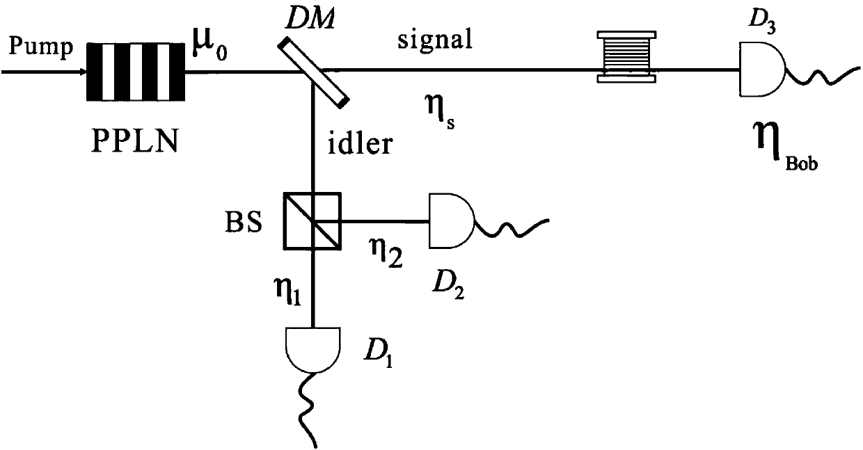
[0023] where |n> represents an n photon state, P n is the corresponding photon number distribution, in the present invention P n It obeys the Poisson distribution; I and S represent leisure light and signal light respectively. Usually leisure light (mode I) is detected locally by Alice at the transmitting end, while signal light (mode S) is sent to Bob at the receiving end.

[0024] The scheme for generating passive HSPS of the present invention is explained below. The main process can be divided into the following steps: the first step, after the parametric down-conversion process, the leisure light is divided into two parts after pass...

Embodiment 2

[0041] For the sake of simplicity in the experiment, only three events such as x, y, z are used to estimate the key extraction rate. The parameters used in the experiment satisfy 010 20 0 1 =tη 10 , η 2 =(1-t)η 20 , with η 1 >0,1-η 2 >0,1-η 1 -η 2 >0. due to d 1 >>1, for any n≥2, we can get:

[0042]

[0043] So for any n≥2 the following inequalities hold:

[0044]

[0045] Using the above formula and considering statistical fluctuations, the lower bound Y of the single photon responsivity can be obtained 1 L and an upper bound on the single-photon bit error rate

[0046]

[0047] where e 0 (=0.5) and Y 0 Respectively represent the qubit bit error rate and dark count at Bob's end in the vacuum state. Q ξ and E ξ (ξ=x, y, z) represent the total response rate and qubit error in any ξ state, respectively;

[0048]

[0049] γ is the standard deviation of statistical fluctuation analysis, which is assumed to be a constant γ=5.3, and the correspondin...


PUM


Abstract

The present invention discloses a quantum cryptography implementation method based on a quantum light source. The method comprises the following steps: generating a labeled single photon source through a PDC process, transmitting signal light to a receiving end, and allowing casual light to be used for local detection. The local detection of the transmitting end comprises a beam splitter (BS), a detector D1 and a detector D2. The casual light passes by the beam splitter to trigger the two detectors to generate four different response events. The four different response events are recorded andused for estimation and processing the signal received by the receiving end, so as to extract a secret key. Due to the usage of a novel passive decoy method, the single photon response rate and bit error rate can be estimated accurately. With a low-loss unequal-arm MZ interferometer used, the consumption of the system is greatly reduced. The single-mode standard commercial light enables the QKD system transmission distance to be over 200 km and based on a quantum light source, so that the final secret key extraction rate is two orders higher than that in the previous QKD system using the quantum light source.

Description

technical field [0001] The invention relates to a quantum cryptography realization method based on a quantum light source, in particular to a quantum light source, which is suitable for application technical fields such as quantum communication and quantum cryptography. Background technique [0002] Based on the theory of quantum mechanics, QKD (Quantum Key Distribution, Quantum Key Distribution) can send keys between legitimate communication parties (Alice and Bob) in an unconditional and secure manner, combined with the one-time pad algorithm in modern cryptosystems, thus It can realize unconditional and secure confidential information transmission. But in fact, due to the unsatisfactory light source, equipment, transmission channel, etc., the eavesdropper (Eve) can take advantage of these shortcomings to take corresponding attacks, so the absolute security endowed by quantum mechanics cannot be realized. To address the above shortcomings, time-shift attacks, photon numbe...

Claims


Application Information

Patent Timeline
Patent Type & Authority Applications(China)
IPC IPC(8): H04L9/08H04B10/70
CPCH04B10/70H04L9/0852
Inventor 王琴张春辉丁华健张春梅
Owner NANJING UNIV OF POSTS & TELECOMM
Learn More