Grating measurement device
A kind of grating measurement and grating technology, which is applied in the direction of measuring device, adopting optical device, converting sensor output, etc., can solve the problems of small vertical measurement range, inability to form effective interference, limited measurement range and spot size, etc., and achieve reduction The size of the transparent surface, the effect of improving energy utilization and compact size
- Summary
- Abstract
- Description
- Claims
- Application Information
AI Technical Summary
Problems solved by technology
Method used
Image
Examples
Embodiment 1
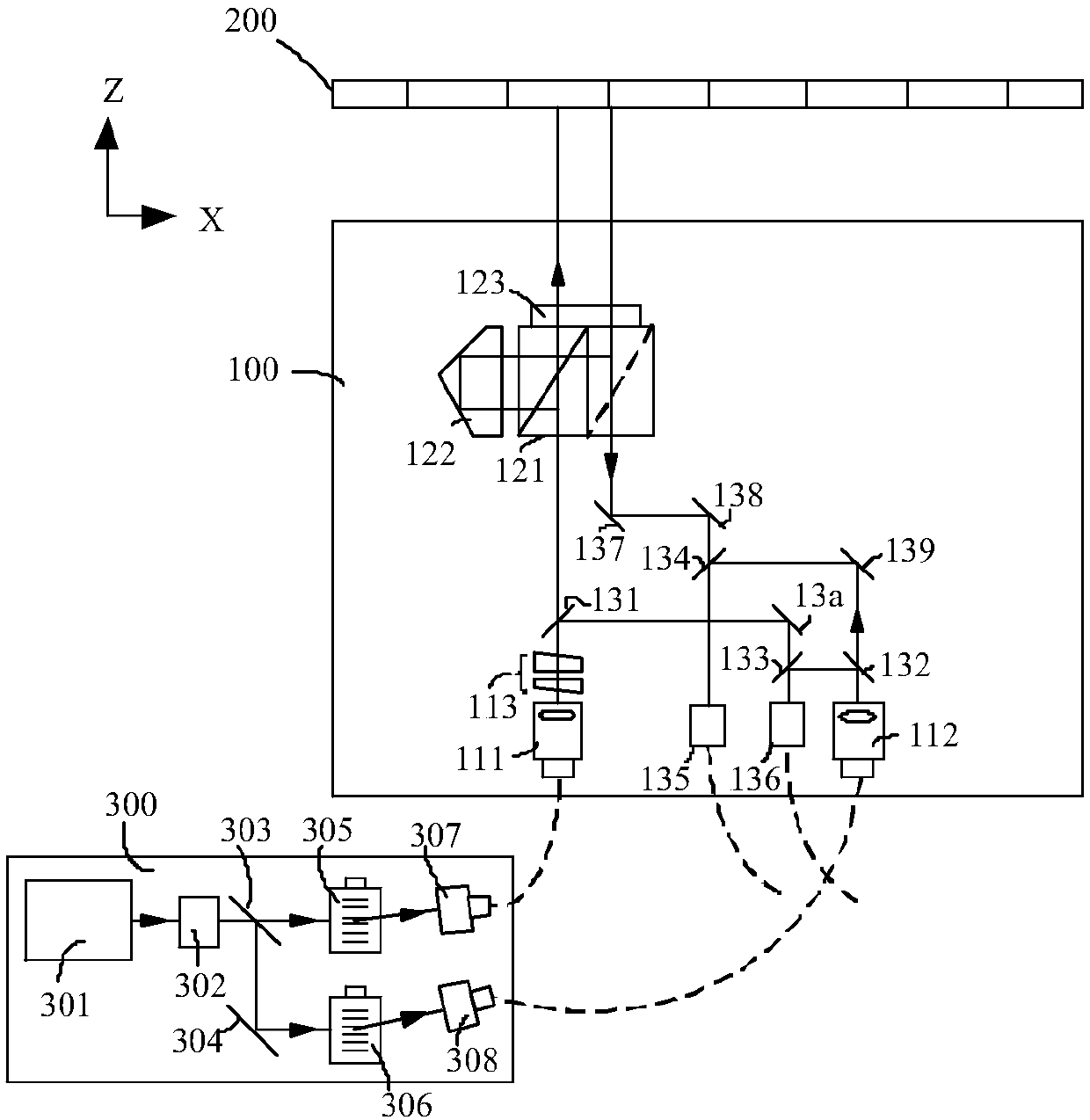
[0053] Such as figure 1 As shown, the grating measuring device of the present embodiment includes:
[0054] The light source module 300 is used to generate two beams with different frequencies. For the sake of distinction, one of the two beams is called a measurement beam, and the other beam is called a reference beam;
[0055] Grating 200;
[0056] first detector;
[0057] second detector;
[0058] as well as
[0059] The grating measurement probe 100 includes a dual-frequency incident light module, a vertical detection module, a vertical measurement module and a reference detection module, wherein the dual-frequency light incident module is used to receive the measurement beam and the reference beam, and project the measurement beam To the vertical measurement module and the reference detection module, the reference beam is projected onto the vertical detection module and the reference detection module, the vertical measurement module projects the measurement beam onto t...
Embodiment 2
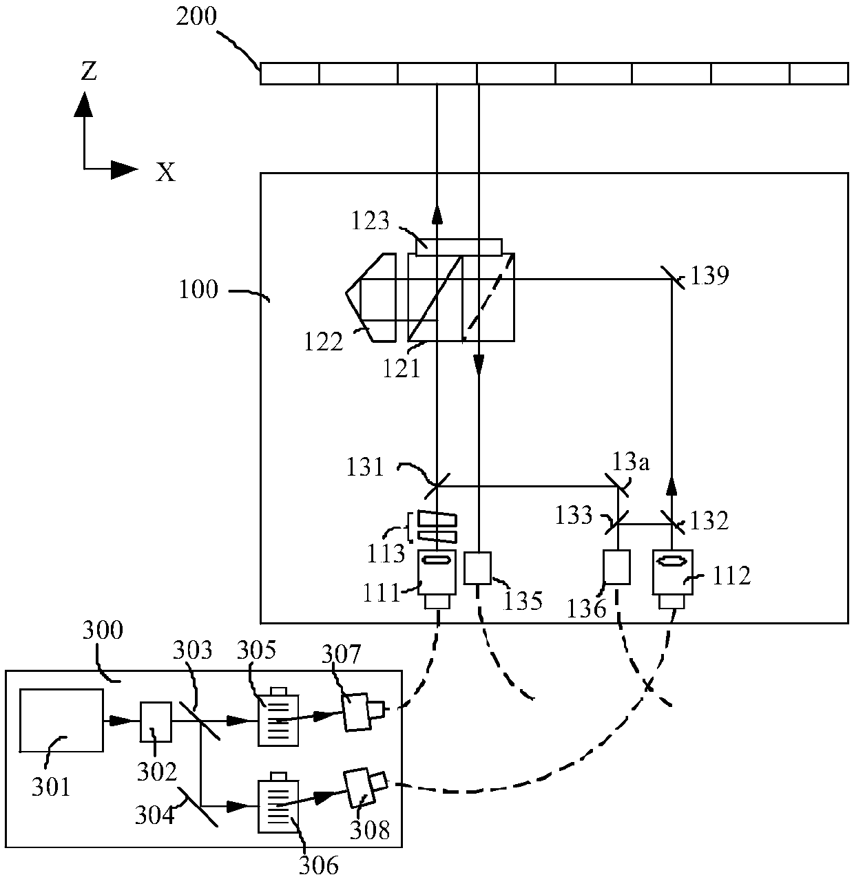
[0077] The difference between this embodiment and Embodiment 1 lies in that the route of the reference beam is different.
[0078] Such as figure 2 As shown, compared with Embodiment 1, the vertical detection module has fewer first and second reflectors 137 and 138 and a fourth beam splitter 134 . Specifically: after the reference beam is collimated by the second collimator 112, it is divided into two beams by the second beam splitter 132, and one of the reference beams is projected to the polarization of the vertical measurement module 120 by the third reflector 139. In the beam-splitting prism 121 , it merges with a measurement split beam, projects it onto the grating 200 , and returns the zero-order beam to the first remote coupler 135 . Another reference split beam merges with another measurement split beam through the third beam splitter 133 and is projected to the second remote coupler 136 . Other parts of the structure and working principles of this embodiment are th...
Embodiment 3
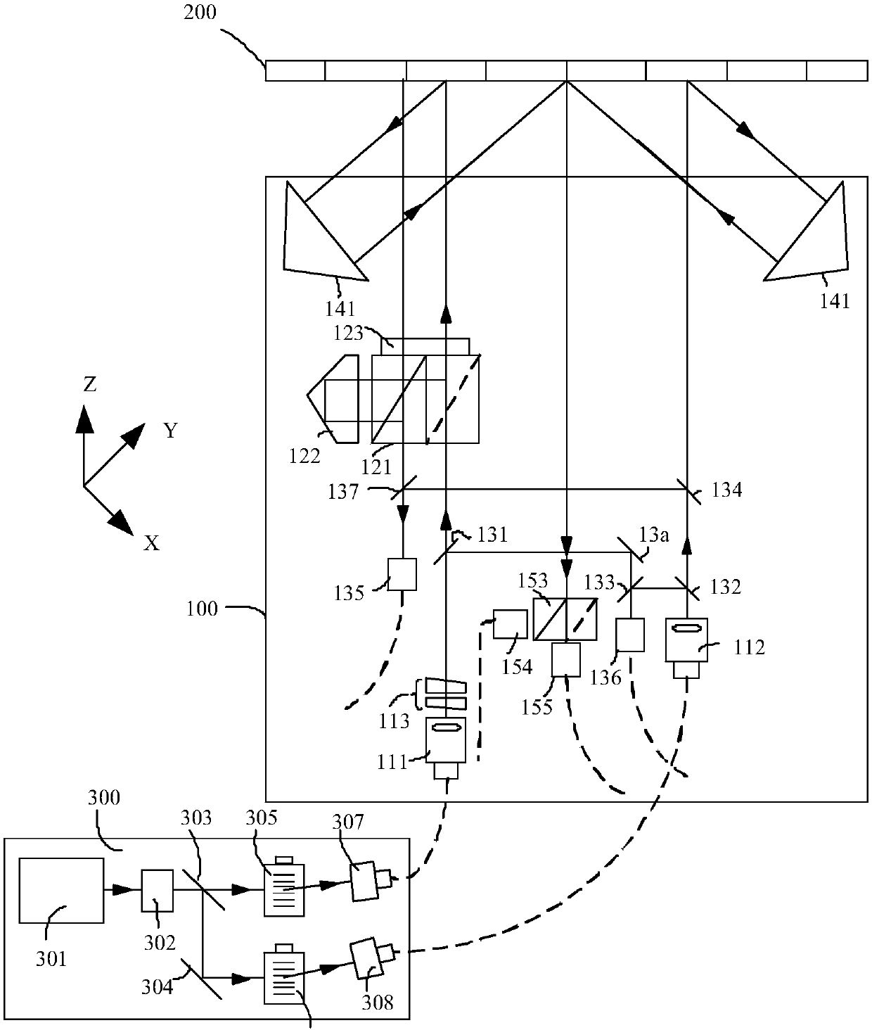
[0080] The difference between this embodiment and Embodiments 1 and 2 is that this embodiment can not only realize vertical measurement, but also can realize horizontal displacement measurement.
[0081] Such as image 3 As shown, the grating measurement device of this embodiment includes: a light source module 300, a grating measurement probe 100, a grating 200, and a plurality of detectors connected to the grating measurement probe 100. 100 inputs two light beams with different frequencies. After being detected by the grating 200, the grating measuring probe 100 outputs position information with X, Y, Z and a reference signal to the detector through a multimode optical fiber.
[0082] Such as image 3 As shown, compared with Embodiment 1, this embodiment adds a horizontal direction detection module and a horizontal direction measurement module, wherein the horizontal direction measurement module includes two symmetrically arranged first corner cubes, and the first corner cu...
PUM
 Abstract
Description
Claims
Application Information
 - R&D
- Intellectual Property
- Life Sciences
- Materials
- Tech Scout
- Unparalleled Data Quality
- Higher Quality Content
- 60% Fewer Hallucinations
Browse by: Latest US Patents, China's latest patents, Technical Efficacy Thesaurus, Application Domain, Technology Topic, Popular Technical Reports.
© 2025 PatSnap. All rights reserved.Legal|Privacy policy|Modern Slavery Act Transparency Statement|Sitemap|About US| Contact US: help@patsnap.com


