
Laser welding machine for automobile part machining

A technology for laser welding machines and auto parts, used in laser welding equipment, welding equipment, metal processing equipment, etc., can solve the problems of insufficient fixation, large welding seam width, and welding seam offset, etc., to achieve tight connection, welding seam and other problems. Flat and beautiful effect

Inactive Publication Date: 2018-02-09
天津市连兴达机械设备有限公司
View PDF0 Cites 0 Cited by
  • Summary
  • Abstract
  • Description
  • Claims
  • Application Information

AI Technical Summary

Problems solved by technology

Because the existing laser welding machine does not fix the two pieces of weldment tightly enough, it is easy to cause problems such as large weld width, weak welding, and weld offset during welding; the existing laser welding machine, the speed of weldment movement The adjustment is not accurate enough, resulting in the weld seam not being smooth and beautiful; the existing laser welding is generally used to monitor the weldment by visual inspection, it is difficult to find welding pores, and the monitoring of waste parts is not in place

Method used


Image

  • Laser welding machine for automobile part machining
  • Laser welding machine for automobile part machining
  • Laser welding machine for automobile part machining

Examples


Embodiment 1

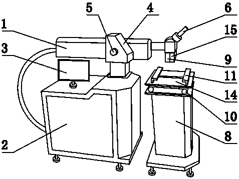
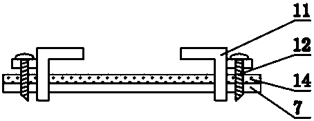
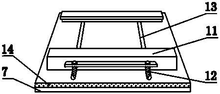
[0011] The present invention is a laser welding machine for auto parts processing, comprising a host 1, a chiller 2, an observation screen 3, a control panel 4, a switch button 5, a microscope 6, a workbench 7, a workbench base 8, a focusing lens 9, a conveyor belt 10, Fixture 11, fixture screw 12, fixture slideway 13, photosensitive plate 14, infrared generator 15, host 1 is installed above chiller 2, observation screen 3 is installed above chiller 1, observation screen 3 is located on the side of host 1, and on the side of host 1 The control panel 4 is installed on the side, the switch button 5 is installed on the side of the control panel 4, the microscope 6 is installed on the side of the host 1, the focusing lens 9 is installed under the microscope 6, and the infrared generator 15 is installed under the microscope 6, and the infrared generator 15 is located on the side of the focusing lens 9 On the side of the chiller 2, a workbench base 8 is installed. A conveyor belt 10 ...

Embodiment 2

[0013] When in use, lay the two pieces of weldment to be welded on the inside of the fixture 11, start the power supply, control the fixture 11 to slide along the fixture slideway 13 through the control panel 4, tighten the fixture 11 in a parallel direction, and the control panel 4 controls the fixture screw 12 to move forward. Turn clockwise, the clamp screw 12 drives the clamp 11 to move downward, and tightens the clamp 11 vertically. At this time, the two weldments are firmly stuck in the clamp 11. Press the switch button 5, and the laser in the host 1 is transmitted through the optical fiber. , collimated into parallel light, then converged by the focusing lens 9, and emitted at the gap between the two weldments, the conveyor belt 10 is controlled by the control panel 4 to drive the workbench 7 to drive at a constant speed, and the two weldments are driven accordingly, and the docking position of the weldments Pass under the focusing lens 9 at a constant speed, press the s...


PUM


Abstract

The invention provides a laser welding machine for auto parts processing, which includes a main machine, a chiller, an observation screen, a control panel, a switch button, a microscope, a workbench, a workbench base, and a focusing lens, and is characterized in that it also includes a conveyor belt, a clamp, and clamp screws , fixture slideway, photosensitive plate, infrared generator, a host machine is installed above the chiller, and an observation screen is installed above the chiller. The present invention improves the traditional laser welding machine for auto parts processing, and sets the infrared generator The control panel controls the infrared generator to emit infrared rays to the welded parts. If there are gaps or pores in the weld, the infrared rays will pass through the gaps or pores and shoot to the photosensitive plate. The photosensitive plate senses the infrared rays and will The signal is sent to the viewing screen, notifying the operator of the detected reject.

Description

technical field [0001] The invention relates to a processing device for automobile parts, in particular to a laser welding machine for processing automobile parts. Background technique [0002] Laser welding is the use of high-energy laser pulses to locally heat materials in a small area. The energy of laser radiation diffuses into the interior of the material through heat conduction, and the material is melted to form a specific molten pool. It is a new type of welding method, mainly aimed at the welding of thin-walled materials and precision parts, which can realize spot welding, butt welding, lap welding, sealing welding, etc., with high depth-to-width ratio, small weld width, and small heat-affected zone. The deformation is small, the welding speed is fast, the weld seam is smooth and beautiful, no treatment is required or only simple treatment is required after welding, the quality of the weld seam is high, the focused light spot is small, and it is easy to realize auto...

Claims


Application Information

Patent Timeline
Patent Type & Authority Applications(China)
IPC IPC(8): B23K26/70
CPCB23K26/702
Inventor 张志利
Owner 天津市连兴达机械设备有限公司
Learn More