
Single-mode optical fiber with low attenuation and large effective area

An effective area, single-mode fiber technology, applied in clad fibers, multi-layer core/clad fibers, light guides, etc. Attenuation coefficient, good dispersion, effect of reducing specific gravity

Inactive Publication Date: 2018-02-09
YANGTZE OPTICAL FIBRE & CABLE CO LTD
View PDF7 Cites 15 Cited by
  • Summary
  • Abstract
  • Description
  • Claims
  • Application Information

AI Technical Summary

Problems solved by technology

However, because of the conventional fluorine outer cladding design, the core layer is still relatively viscous than the fluorine outer cladding, and defects are still prone to occur during the wire drawing process, which limits the further reduction of fiber attenuation performance. In addition, the fluorine outer cladding structure is adopted. Due to the fluorine The cost of doping is high, and the viscosity is very low. In the process of preparing and drawing optical fiber preforms, the preparation process of preforms with pure silica outer cladding is more complicated, the process control progress is higher, and the cost is higher.

Method used


Image

  • Single-mode optical fiber with low attenuation and large effective area
  • Single-mode optical fiber with low attenuation and large effective area
  • Single-mode optical fiber with low attenuation and large effective area

Examples


Embodiment Construction

[0036] The present invention will be further described and illustrated in detail below in conjunction with embodiments.

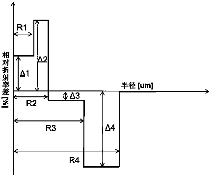
[0037] The refractive index profile structure distribution of an embodiment of the present invention is as figure 1 As shown, including a core layer and a cladding layer, the core layer includes a depressed inner core layer and an outer core layer, the depressed inner core layer is located at the center of the optical fiber, and the radius is r 1 , The relative refractive index difference is Δn 1 , The outer core layer tightly wraps the sunken inner core layer, the radius is r 2 , The relative refractive index difference is Δn 2 The core layer is covered with a cladding layer, the cladding layer includes an inner cladding layer, a sinking cladding layer and an outer cladding layer from the inside to the outside, and the inner cladding layer has a radius of r 3 , The relative refractive index difference is Δn 3 , The radius of the sunken cladding is r 4 , The re...


PUM


Abstract

The invention relates to a single-mode optical fiber with low attenuation and large effective area. The single-mode optical fiber comprises a core layer and a wrapping layer, and is characterized in that the core layer comprises a sunken inner core layer and an outer core layer, the radius r1 of the sunken inner core layer is 2.2 - 3.5 microns, delta n1 is 0. 08% - 0. 20%, the radius r2 of the outer core layer is 5 -6.5 microns, delta n2 is 0.20%-0.32%, the wrapping layer wraps outside the core layer, the wrapping layer sequentially comprises an inner wrapping layer, a sunken wrapping layer and an outer wrapping layer from inside to outside, the radius r3 of the inner wrapping layer is 9 -13 microns, delta n3 is -0.06% -0.06%, the radius r4 of the sunken wrapping layer is 11-18 microns, and the delta n4 is -0.60%- -0.35%; and the outer wrapping layer is a pure silicon dioxide glass layer. A sunken structure of the central core layer is arranged, so that the internal energy distributionof an optical fiber is changed from the typical gaussian distribution to the non-gaussian distribution, and the effective area of the optical fiber is effectively increased on the basis that the cut-off wavelength and the dispersion performance of the optical fiber are ensured. The optical fiber is low in attenuation and large in effective area. The optical fiber is low in manufacturing cost andhas relatively good bending loss and dispersion performance.

Description

Technical field [0001] The invention relates to the field of optical fiber transmission, in particular to a single-mode optical fiber with low attenuation and large effective area, which is used in a long-distance, large-capacity, and high-speed transmission system. Background technique [0002] With the emergence of coherent transmission technology, in the field of optical fiber transmission, some important indicators that originally restricted long-distance, large-capacity, and high-speed transmission no longer become restrictions. In the future transmission system, chromatic dispersion (CD) and polarization mode dispersion ( PMD) indicators can be further relaxed. However, the attenuation and effective area of ​​optical fibers are still important issues that limit the development of optical communication technology. [0003] Especially in the future transmission system of 400G or higher, the reduction of attenuation will greatly reduce the construction and maintenance cost of t...

Claims


Application Information

Patent Timeline
Patent Type & Authority Applications(China)
IPC IPC(8): G02B6/036
CPCG02B6/03611
Inventor 张磊吴超王瑞春朱继红汪洪海
Owner YANGTZE OPTICAL FIBRE & CABLE CO LTD
Learn More