Negative plate for lithium slurry battery

A slurry battery and negative electrode technology, which is applied in the direction of non-aqueous electrolyte battery electrodes, negative electrodes, secondary batteries, etc., can solve the problems of consumption of electrolyte and active lithium, deterioration of battery cycle performance, battery short circuit, etc., and achieve current distribution Uniformity, avoiding heating phenomenon, improving energy density and efficiency

Active Publication Date: 2018-02-09
南京竞予能源有限公司
View PDF7 Cites 24 Cited by
  • Summary
  • Abstract
  • Description
  • Claims
  • Application Information

AI Technical Summary

Problems solved by technology

[0004] In the lithium slurry battery mentioned in Chinese invention patent CN201610074921.1, the electronically conductive negative electrode current collector is close to the isolation layer of the battery, so that lithium ions are easily deposited on the surface of the negative electrode current collector when the battery is charged and discharged at a large rate and overcharged. There is thus a danger of "lithium dendrites" piercing the separator and causing an internal short circuit in the battery
In addition, the Chinese invention patent CN201510164222.1 proposes a lithium slurry battery in which the negative electrode current collector is placed inside the negative electrode reaction chamber. This battery has the following problems, that is, the negative electrode slurry is accompanied by the formation of the SEI film during the first and subsequent cycles. Destruction and repair, this process will consume electrolyte and active lithium, resulting in deterioration of battery cycle performance

Method used


Image

  • Negative plate for lithium slurry battery
  • Negative plate for lithium slurry battery
  • Negative plate for lithium slurry battery

Examples


Embodiment Construction

[0045] In the following, the present invention will be further described through embodiments with reference to the accompanying drawings.

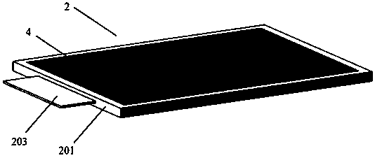
[0046] figure 1 It is a schematic diagram of the lithium paste battery according to the present invention. The cell of the lithium slurry battery includes several alternately arranged sandwich composite positive electrode sheet 1 and negative electrode sheet 2. An isolation cavity 3 with a height of 0.1mm~1mm is arranged between the sandwich composite positive electrode sheet 1 and the negative electrode sheet 2. The isolation cavity 3 It is filled with electrolyte. The sandwich composite positive electrode sheet 1 includes a porous current-collecting positive electrode layer 101 and a conductive slurry 102. The porous current-collecting positive electrode layer 101 is composed of a porous positive electrode current collector coated with a porous positive electrode material layer on one or both sides, and two porous current collector positive...


PUM

PropertyMeasurementUnit
thicknessaaaaaaaaaa
pore sizeaaaaaaaaaa
pore sizeaaaaaaaaaa

Abstract

The invention provides a negative plate for a lithium slurry battery. The negative plate comprises an insulated sealing frame, a lithium-containing metal body and an intercalated lithium collector structure layer, wherein the intercalated lithium collector structure layer, the lithium-containing metal body and another intercalated lithium collector structure layer form a sandwich composite structure; the insulated sealing frame seals the surrounding margins of the sandwich composite structure; and the material of the intercalated lithium collector structure layer contains the lithium intercalated material which can intercalate lithium in the charge and discharge process of the lithium slurry battery. The intercalated lithium collector structure layer in the negative plate can play the roleof intercalating lithium during charging, and avoid the deposition of lithium on the surface of the lithium-containing metal body to form lithium dendrites, thereby improving the safety of the battery. Besides, the lithium-containing metal body can also be used as a lithium source to effectively supplement the consumption on positive electrode lithium of the side reaction in the process of negative SEI membrane formation and battery cycle. In addition, a common collector of the lithium-containing metal body and the intercalated lithium collector structure layer makes the current collection effect uniform, and avoids the occurrence of heating and so on caused by high-rate charge and discharge.

Description

Technical field [0001] The invention belongs to the technical field of electrochemical power batteries, and specifically relates to a negative electrode sheet of a lithium slurry battery. Background technique [0002] Lithium-ion battery is a new type of high-energy battery with lithium intercalation compound as the positive and negative electrode materials. Compared with lead-acid batteries and nickel-hydrogen batteries, it has a series of high specific energy, high voltage, low self-discharge, good cycle performance and long life. The advantages have attracted more and more attention. In recent years, lithium-ion battery technology has achieved rapid development and has begun to be used in electric vehicles. [0003] A lithium slurry battery contains electrode sheets and electrolyte. After the electrolyte is injected, a conductive slurry is formed inside the positive sheet and / or negative sheet of the battery. The conductive slurry contains a certain proportion of conductive par...

Claims


Application Information

Patent Timeline
Patent Type & Authority Applications(China)
IPC IPC(8): H01M4/13H01M10/0525
CPCH01M4/13H01M10/0525H01M2004/027Y02E60/10
Inventor 陈永翀何颖源张彬张艳萍张萍
Owner 南京竞予能源有限公司
Why Eureka
Try Eureka