Negative resistor-based series-parallel wireless power transmission system

A technology of wireless power transmission and negative resistance, applied in the direction of electrical components, circuit devices, etc., can solve the problems of short transmission distance, low output power, low operating frequency, etc., and achieve stable wireless power transmission, high efficiency, and simple system structure Effect

Pending Publication Date: 2018-02-09
SOUTH CHINA UNIV OF TECH
View PDF0 Cites 0 Cited by
  • Summary
  • Abstract
  • Description
  • Claims
  • Application Information

AI Technical Summary

Problems solved by technology

In order to meet the development trend of high-frequency and high-efficiency wireless power transmission systems, switch-type driving sources (power amplifiers) such as class D and class E power amplifiers are usually used. Although the theoretical efficiency of this type of power amplifier reaches 100%, the output Low power, only suitable for low power applications
At present, bridge inverters composed of IGBT and MOSFET tubes are mostly used in high-power applications, and different soft-switching algorithms are used to realize wireless transmission of electric energy, but its operating frequency is low and the transmission distance is short.
Therefore, restricted by factors such as power switching tubes and circuit topology, it is still quite difficult to realize high-frequency (above MHz), high-reliability, and high-power switching converters under the existing technical conditions.

Method used


Image

  • Negative resistor-based series-parallel wireless power transmission system
  • Negative resistor-based series-parallel wireless power transmission system
  • Negative resistor-based series-parallel wireless power transmission system

Examples


Embodiment Construction

[0015] The present invention will be further described below in conjunction with specific examples.

[0016] The basic principle of the series-parallel wireless power transfer system based on negative resistance provided in this embodiment is to use the negative resistance to release energy and provide electrical energy to the outside, which is used to replace the traditional series-parallel wireless power transfer system The high-frequency power source effectively solves the technical problem that the current high-frequency and high-power switching converters are difficult to realize.

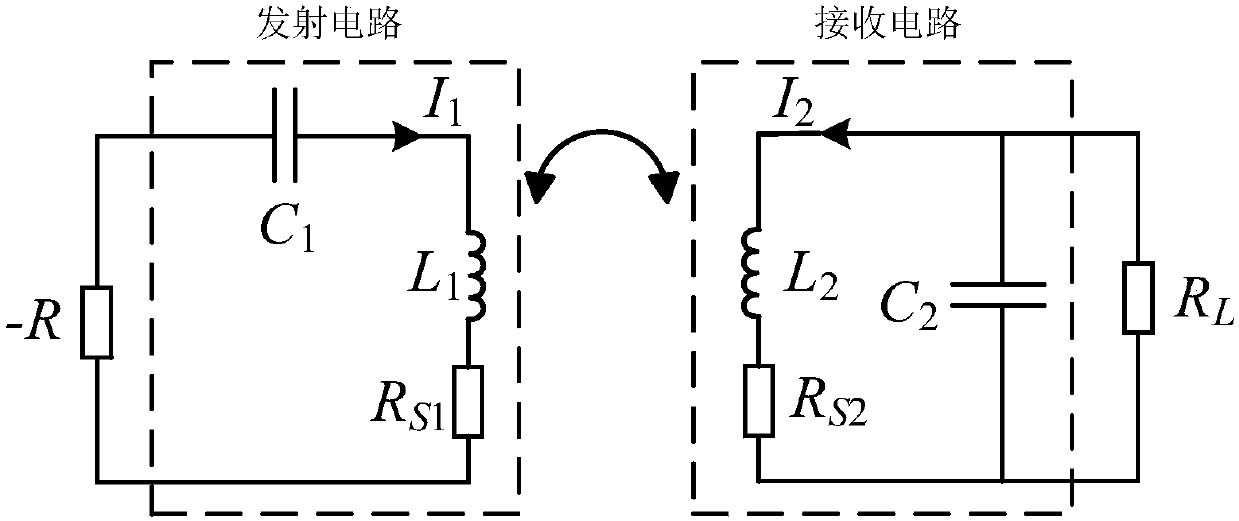
[0017] Such as figure 1 As shown, it is the specific implementation circuit of this system, including the connected negative resistance-R and the transmitting circuit, as well as the connected receiving circuit and load R L , the transmitting circuit and the receiving circuit realize the wireless transmission of electric energy through electromagnetic induction coupling; the transmitting circ...


PUM


Abstract

The invention discloses a negative resistor-based series-parallel wireless power transmission system, which comprises a negative resistor and a transmitting circuit which are connected with each other, and a receiving circuit and a load which are connected with each other, wherein the transmitting circuit comprises a primary side capacitor and a primary side transmitting coil which are connected in series; the primary side transmitting coil comprises a primary side inductor and a transmitting circuit internal resistor which are connected in series; the transmitting circuit internal resistor refers to all positive resistors, except for the resistors reflected to a primary side from a secondary side, of the transmitting circuit; the receiving circuit comprises a secondary side receiving coiland a secondary side capacitor which are connected in parallel; the secondary side receiving coil comprises a secondary side inductor and a receiving circuit internal resistor which are connected inseries; and the receiving circuit internal resistor refers to all positive resistors, except for the load, of the receiving circuit. Energy supply for the circuits is achieved by using the property that energy is generated by the negative resistor, so that a high-frequency inverter source in a traditional series-parallel wireless power transmission system is replaced, and the system is simpler instructure, higher in working frequency and more stable in transmission efficiency.

Description

technical field [0001] The present invention relates to the field of wireless power transmission or wireless power transmission technology, in particular to a series-parallel wireless power transmission system based on negative resistance. Background technique [0002] Wireless power transmission technology can realize complete electrical isolation between power supply and electrical equipment, and has the advantages of safety, reliability and flexibility. As early as the end of the 19th century, Nikola Tesla used the principle of wireless power transmission to light up a light bulb without any wire connection. Wireless power transmission based on magnetic coupling resonance is a breakthrough made by MIT scholars in the field of wireless power transmission. Since it was published in 2007, it has aroused great repercussions in the field of wireless power transmission. More and more scholars Join in the basic research and application development of wireless power transfer tec...

Claims


Application Information

Patent Timeline
IPC IPC(8): H02J50/12
CPCH02J50/12
Inventor 张波疏许健韩冲周佳丽
Owner SOUTH CHINA UNIV OF TECH
Why Eureka
Try Eureka