Sealed urea heating pipe

A heating tube, sealed technology, applied in the field of components of automobile exhaust gas treatment system, can solve the problems of unsatisfactory heating effect, signal unable to be recognized and captured by computer, SCR exhaust gas treatment system unable to operate normally, etc. , the effect of uniform heating

Inactive Publication Date: 2018-02-13
湖北拓威汽车尾气系统有限公司
View PDF1 Cites 1 Cited by
  • Summary
  • Abstract
  • Description
  • Claims
  • Application Information

AI Technical Summary

Problems solved by technology

[0005] The above-mentioned patent document uses a heating belt on the outer wall of the conveying pipeline. Under extreme conditions of around -50°C, the heating effect is not ideal, resulting in the failure of the SCR exhaust gas treatment system to operate normally, often accompanied by signals that cannot be recognized by the computer. and capture

Method used


Image

  • Sealed urea heating pipe
  • Sealed urea heating pipe

Examples


Embodiment Construction

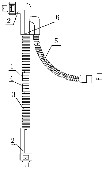
[0022] The present invention as figure 1 , 2 shown.

[0023] A sealed urea heating pipe, comprising a urea liquid return pipe 1, the two ends of the urea liquid return pipe 1 are respectively provided with quick-plug joints 2, and the outside of the urea liquid return pipe 1 is provided with a bellows 2, and the urea liquid return pipe 1 is provided with a bellows 2. A heating wire or a heating belt 4 is arranged outside the liquid return pipe 1, and the heating wire or heating tape 4 wraps the urea liquid return pipe 1 and solidifies the quick-plug joints 2 at both ends, and leads out the plug 5 through the side wall of the quick-plug joint 2 wiring;

[0024] The push-in connector 2 and the urea return pipe 1 are plastic-sealed and cured at one time to form a whole;

[0025] The urea return pipe 1 is provided with a heating wire or a heating belt 4, and the heating wire or heating belt 4 is placed in the center through the push-in connectors 2 at both ends in the urea retu...


PUM


Abstract

The invention relates to a sealed urea heating pipe. Quick inserting joints are arranged at the two ends of a urea liquid return pipe correspondingly. A corrugated pipe is arranged at the exterior ofthe urea liquid return pipe. The urea liquid return pipe is externally provided with a heating wire or a heating band which covers the urea liquid return pipe and cures the quick inserting joints at the two ends. An inserting joint connecting wire is led out through the side wall arranged on each quick inserting joint. The quick inserting joints and the urea liquid return pipe are subjected to one-time plastic sealing and curing. A led inserting joint is further cured on the side wall of the corresponding quick inserting joint, and the led inserting joint and the corresponding quick insertingjoint form a whole. The urea liquid return pipe is internally provided with the heating wire or the heating band which is arranged in the center through the quick inserting joins at the two ends in the urea liquid return pipe. The inserting joint connecting wires are led out through the side walls arranged on the quick inserting joints. The heating wire or the heating band is cured in the quick inserting joins at the two ends in the urea liquid return pipe. According to the sealed urea heating pipe, the whole is formed, beautiful appearance and neatness are achieved, water can never enter theurea pipe, and even if the urea pipe soaked in the water, the water cannot enter the urea pipe, so that it is ensured that the resistance value cannot be increased and high temperature, even an ignition phenomenon, cannot be produced.

Description

technical field [0001] The invention relates to components of an automobile tail gas treatment system, in particular to a sealed urea heating pipe. Background technique [0002] The urea liquid return pipe is the key component of the automobile exhaust gas treatment system. It is thick and heated under low temperature conditions. The existing technology produces and manufactures the urea heating pipe of the SCR exhaust gas treatment system. The heating element is heated outside the pipe, and the heating is not uniform and the heating is not comprehensive. There is a phenomenon of insufficient heating conduction in low temperature environments, especially in extreme conditions around -50°C, the heating effect is not ideal, resulting in the failure of the SCR exhaust gas treatment system to operate normally, often accompanied by signals that cannot be recognized and captured by the computer. [0003] The current urea liquid return pipe has a snap-fit ​​seal, which is easy for ...

Claims


Application Information

Patent Timeline
Patent Type & Authority Applications(China)
IPC IPC(8): F01N3/28
CPCF01N3/2882F01N2240/16
Inventor 刘强刘玉波李国强
Owner 湖北拓威汽车尾气系统有限公司
Why Eureka
Try Eureka