Damping control method in non-electrolytic capacitance permanent-magnet synchronous-motor air conditioning drive system

A technology of permanent magnet synchronous motor and motor drive system, applied in motor generator control, electronic commutation motor control, motor control and other directions, can solve a large number of mathematical derivation, complex and other problems

Active Publication Date: 2018-02-13
HARBIN INST OF TECH
View PDF3 Cites 21 Cited by
  • Summary
  • Abstract
  • Description
  • Claims
  • Application Information

AI Technical Summary

Problems solved by technology

The frequency compensation method first establishes a mathematical model for the motor in the frequency domain, and eliminates resonance on the basis of the mathematical model of the motor. This method requires a lot of mathematical derivation, so it is more complicated

Method used


Image

  • Damping control method in non-electrolytic capacitance permanent-magnet synchronous-motor air conditioning drive system
  • Damping control method in non-electrolytic capacitance permanent-magnet synchronous-motor air conditioning drive system
  • Damping control method in non-electrolytic capacitance permanent-magnet synchronous-motor air conditioning drive system

Examples


specific Embodiment approach 1

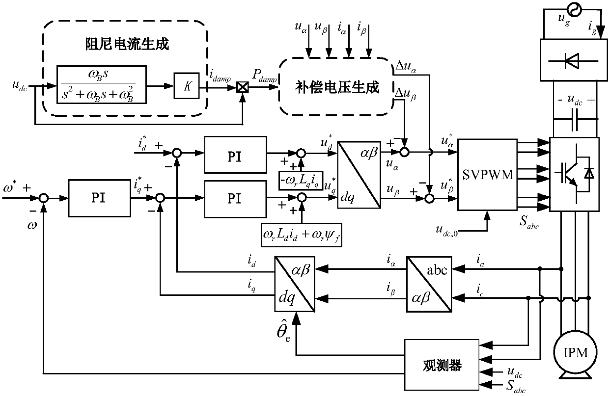
[0080] Specific implementation manner 1: The implementation steps of the damping control method for the resonance phenomenon existing in the electrolytic capacitor permanent magnet synchronous motor drive system are as follows:

[0081] Step 1: The system damping is small. In order to increase the system damping, a damping current can be added in parallel with the inverter current. When the permanent magnet synchronous motor is running, the damping current can be obtained by processing the DC bus voltage with a bandpass filter , And multiply by a coefficient to further adjust the damping characteristics of the system;

[0082] Step 2: Since the frequency of the damping current is often higher than the bandwidth of the inner loop current loop, and the DC bus current is difficult to control, the damping current obtained in step 1 is processed to obtain the equivalent damping power, and the control of the damping power is achieved Damping current control;

[0083] Step 3: Since the dam...

specific Embodiment approach 2

[0085] Embodiment 2: The difference between this embodiment and the above-mentioned embodiment 1 is: the analysis and acquisition of the damping current in parallel with the inverter current in step 1, by passing the DC bus voltage through a The band pass filter is multiplied by a coefficient K to obtain an adjustable damping current to optimize the system operation effect. The specific analysis process is as follows:

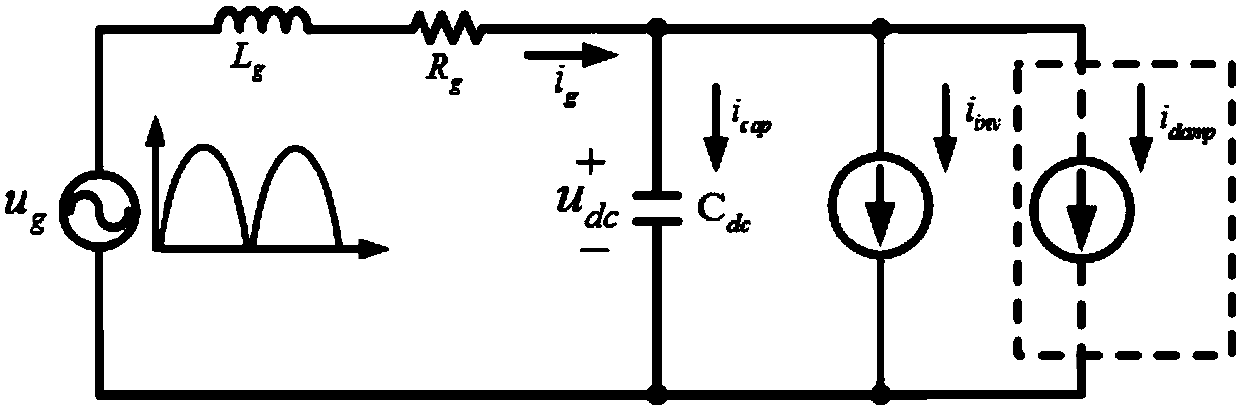
[0086] Such as figure 2 Shown is a simplified circuit diagram of a non-electrolytic capacitor air conditioning drive system obtained after the inverter and the motor are equivalent to a constant current source. In order to improve the damping and stability of the system, the damping current and the inverter current are connected in parallel. The derivation process of the damping current is as follows:

[0087] Input the DC bus voltage into a band-pass filter, and multiply the output of the band-pass filter by a coefficient K to get the damping current. The band pa...

specific Embodiment approach 3

[0099] Embodiment 3: The difference between this embodiment and the second embodiment described above is: the damping current obtained in the embodiment 2 is processed to obtain equivalent damping power, and the damping power is controlled by To realize the control of the damping current;

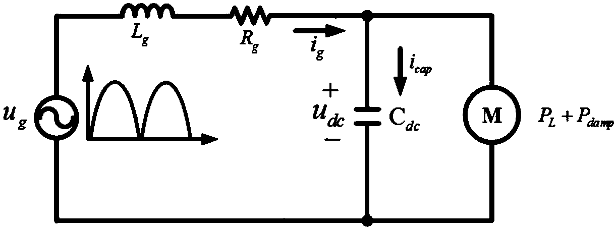
[0100] Because the frequency of the damping current is higher than the frequency of the current loop bandwidth, the damping current cannot be effectively controlled, so the damping power corresponding to the damping current is obtained, and the purpose of improving the damping of the system is achieved by controlling the damping power, thereby eliminating resonance , Stable system. image 3 is true figure 2 Further simplification, such as image 3 As shown, the damping current is represented by damping power, the inverter current is represented by inverter power, and the inverter power is the sum of load power and damping power.

[0101] The expression of damping power is as follows:

[0102] P ...


PUM


Abstract

The invention discloses a damping control method in a non-electrolytic capacitance permanent-magnet synchronous-motor air conditioning drive system and relates to a method for inhibiting resonance inthe built-in permanent-magnet synchronous-motor air conditioning drive system with an aim to solve the problem about resonance generated from interaction of an input side filter and a direct-current bus capacitor of the air conditioning drive system. The damping control method includes: 1), when the permanent-magnet synchronous motor runs, processing direct-current bus voltage by using a band-passfilter and multiplying the direct-current bus voltage by a coefficient K to obtain damping current; 2), performing processing according to the obtained damping current to obtain equivalent damping power and controlling the damping current by controlling the damping power, wherein the expression of the damping power is the damping current multiplied by the direct-current bus voltage; 3), changingoutput power of an inverter to achieve the damping power, generating an extra voltage reference value to have the output power of the inverter changed, and finally, generating an extra voltage commandsignal to have resonance in the system inhibited. The damping control method is applicable to the technical field of motor control.

Description

Technical field [0001] The invention is applied in the technical field of motor control, and particularly relates to a resonance suppression method for a built-in permanent magnet synchronous motor drive system. Background technique [0002] Compared with DC motors and induction motors, permanent magnet synchronous motors are reliable and simple in structure, and have the advantages of high power density and excellent speed regulation performance, so they are widely used. Traditional air-conditioning motor drive systems use large-capacity electrolytic capacitors and PFC circuits on the DC side. The life of electrolytic capacitors is greatly affected by temperature. Most air-conditioning failures are caused by the damage of electrolytic capacitors. The large-capacity electrolytic capacitor can be replaced with a small-capacity film capacitor, so the life of the air conditioning drive system is improved. Since the function of the DC bus capacitor is to store energy and stabilize t...

Claims


Application Information

Patent Timeline
Patent Type & Authority Applications(China)
IPC IPC(8): H02P21/22H02P21/13H02P25/024H02P27/08
CPCH02P21/13H02P21/22H02P25/024H02P27/08H02P2205/03H02P2207/05H02P2209/11
Inventor 王高林赵楠楠于超慧张容驰李斌兴白音徐殿国
Owner HARBIN INST OF TECH
Why Eureka
Try Eureka