Single-anode-electrode double-medium gas source plasma burner

A plasma and dual-medium technology, applied in the direction of gas fuel burners, burners, combustion methods, etc., can solve the problems of high power consumption of secondary energy, and achieve the effects of reducing power consumption, improving use efficiency, and simple ignition methods

Pending Publication Date: 2018-02-16
SHENWU TECH GRP CO LTD
View PDF0 Cites 3 Cited by
  • Summary
  • Abstract
  • Description
  • Claims
  • Application Information

AI Technical Summary

Problems solved by technology

The main heat supply of the existing plasma burner is to ionize the medium gas through electric energy to generate thermal plasma, and to supply heat through the thermal plasma, which consumes a huge amount of electric energy as a secondary energy source.

Method used


Image

  • Single-anode-electrode double-medium gas source plasma burner
  • Single-anode-electrode double-medium gas source plasma burner

Examples


Embodiment 1

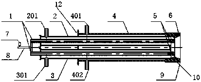
[0039] Embodiment 1: The distance between the air inlet and gas inlet and the arc starting position of the cathode and anode is 800mm, the distance between the inlet and outlet of cooling water and the arc starting position of the cathode and anode is 450mm, and the diameter of the burner sleeve is 150mm. The gas uses air and natural gas as the medium gas respectively, and the design power of the burner is 20kw. In the test results, the thermal power provided by the plasma is 14.3kw, the thermal power provided by combustion is 5.6kw, and the actual operating power is 19.9kw, which is basically the same as the design power. Stable combustion, the air-fuel ratio is controlled between 1:1.01~1.05, the gas flow rate is 50L / min, the cooling water volume is 25L / min, and the cooling water temperature difference is about 1°C.

Embodiment 2

[0040] Embodiment 2: The distance between the air inlet and gas inlet and the arc starting position of the cathode and anode is 800mm, the distance between the cooling water inlet and outlet and the arc starting position of the cathode and anode is adjusted to 600mm, and the diameter of the burner sleeve is 150mm , The gas uses air and natural gas as the medium gas respectively, and the design power of the burner is 20kw. The test results include that the thermal power provided by plasma is 13.5kw, the thermal power provided by combustion is 4.2kw, the actual operating power is 19.2kw, which is 0.8kw different from the designed power, and the temperature after combustion is about 2100°C. Repeated ignition experiment ignition, all can Stable combustion, the air-fuel ratio is controlled between 1:1.01~1.05, the gas flow rate is 50L / min, and the cooling water temperature difference is about 2°C.

Embodiment 3

[0041] Embodiment 3: The distance between the air inlet and gas inlet and the arc starting position of the cathode and anode is 600 mm, the distance between the cooling water inlet and outlet and the arc starting position of the cathode and anode is adjusted to 200 mm, and the diameter of the burner sleeve is 150 mm , The gas uses air and natural gas as the medium gas respectively, and the design power of the burner is 20kw. In the test results, the thermal power provided by the plasma is 14.4kw, the thermal power provided by the combustion is 4.8kw, the actual operating power is 17.7kw, which is 2.3kw different from the design power, and the temperature after combustion is about 2500°C. Repeated ignition experiments can be ignited. Stable combustion, the air-fuel ratio is controlled between 1:1.01~1.05, the gas flow rate is 50L / min, and the cooling water temperature difference is about 0.8°C.


PUM


Abstract

The invention belongs to the technical field of plasma burners that can be used in petrochemical, metallurgical, and electric power industries, and specifically relates to a single-anode dual-medium gas source plasma burner, including: two cathode channel tubes, air tubes, gas tubes, and burners Bushing, cathode, anode and other components, the present invention adopts discharge arc between two separate cathodes and the same anode to ionize two different medium gases, and generates At the same time, part of the fuel can be burned during the plasma, which indirectly replaces part of the electric energy and improves the use efficiency of secondary energy.

Description

technical field [0001] The invention belongs to the technical field of plasma burners that can be used in petrochemical, metallurgical and electric power industries, and in particular relates to a single-anode double-medium gas source plasma burner. Background technique [0002] Plasma refers to a highly active substance containing a large number of electrons, ions, excited molecules, atoms and free radicals produced by ionization of gas, also known as the "fourth state" of matter. The temperature range of low-temperature plasma is from several thousand to Tens of thousands of degrees, that is, thermal plasma. Thermal plasma is used in industry. It can be used as an ignition gun for pulverized coal boilers, gasification of garbage and solid waste, etc., ignition and stable combustion of gas turbines, and hydrogen production in chemical industry. There has also been a great deal of research on the use of thermal plasmas to prepare materials such as graphene. [0003] At pres...

Claims


Application Information

Patent Timeline
Patent Type & Authority Applications(China)
IPC IPC(8): F23D14/02F23D14/46
CPCF23D14/02F23D14/46
Inventor 石为华王晶晨王志军郭科宏钟贵全吴道洪
Owner SHENWU TECH GRP CO LTD
Why Eureka
Try Eureka