
Coupling spiral cleaning type natural circulation evaporator

A technology of natural circulation and evaporator, applied in the direction of flushing, cleaning heat transfer devices, lighting and heating equipment, etc., can solve the problems that cannot be popularized and applied, the particle external circulation system is complex, and the cleaning capacity is large

Active Publication Date: 2018-02-16
浙江建装工程技术研究有限公司
View PDF8 Cites 5 Cited by
  • Summary
  • Abstract
  • Description
  • Claims
  • Application Information

AI Technical Summary

Problems solved by technology

For example, the literature (China Well Mine Salt 2012 No. 1: Three-phase flow evaporation anti-scaling and energy-saving technology; inorganic salt industry 2008 No. 8 anti-scaling technology for evaporation equipment and its application in the production of calcium chloride) introduction The gas-liquid-solid three-phase fluidization technology has a large cleaning ability, but the technology is difficult (difficult to uniformly distribute the particles in the tube bundle, and the external circulation system of the particles is complicated), and the fluidized particles are inevitably mixed into the crystalline salt, which seriously threatens the quality of the product. Eligibility issues, unable to promote the application
The paper (Research on Automatic Cleaning Technology of Crystallized Salt in Heating Tube of Salt Evaporator. Haihu Salt and Chemical Industry, 2001, 30(4): 28-30) introduced the plastic twisted belt automatic cleaning technology, which is not effective in the high temperature of evaporation production. Meet the engineering requirements of evaporation production

Method used


Image

  • Coupling spiral cleaning type natural circulation evaporator
  • Coupling spiral cleaning type natural circulation evaporator
  • Coupling spiral cleaning type natural circulation evaporator

Examples


Embodiment Construction

[0012] In order to illustrate the technical solution of the present invention more clearly, the technical solution of the present invention will be further described in detail below in conjunction with the accompanying drawings and embodiments. Obviously, the following descriptions are only some embodiments of the present invention. In other words, other embodiments can also be obtained according to these embodiments without paying creative efforts.

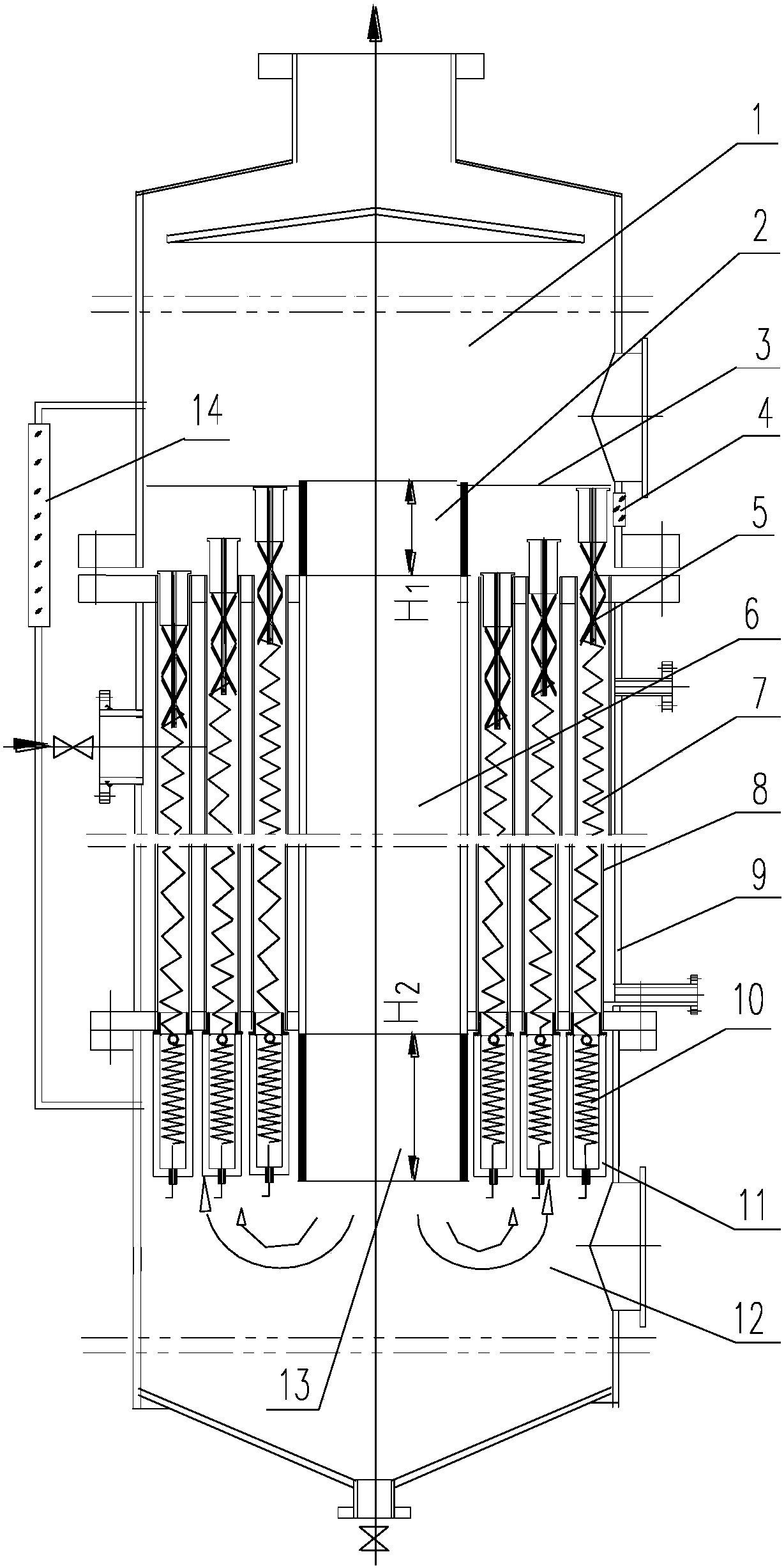
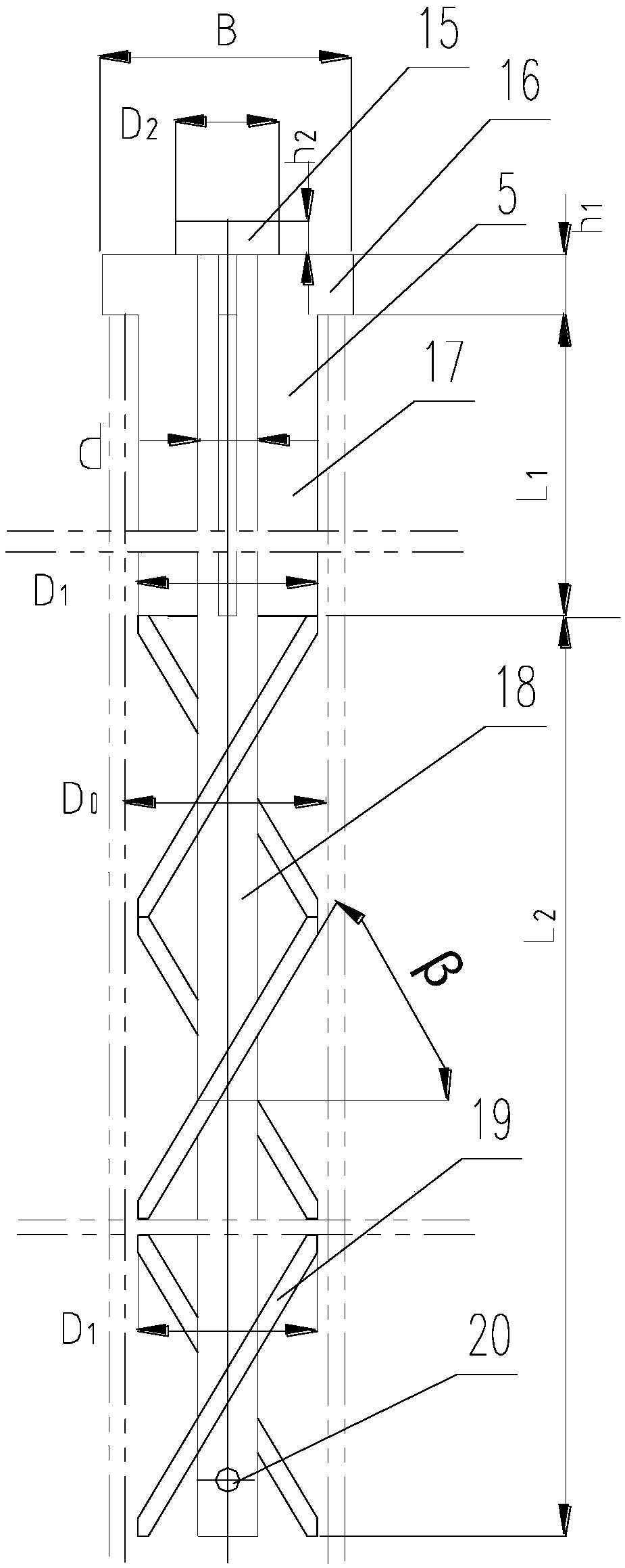
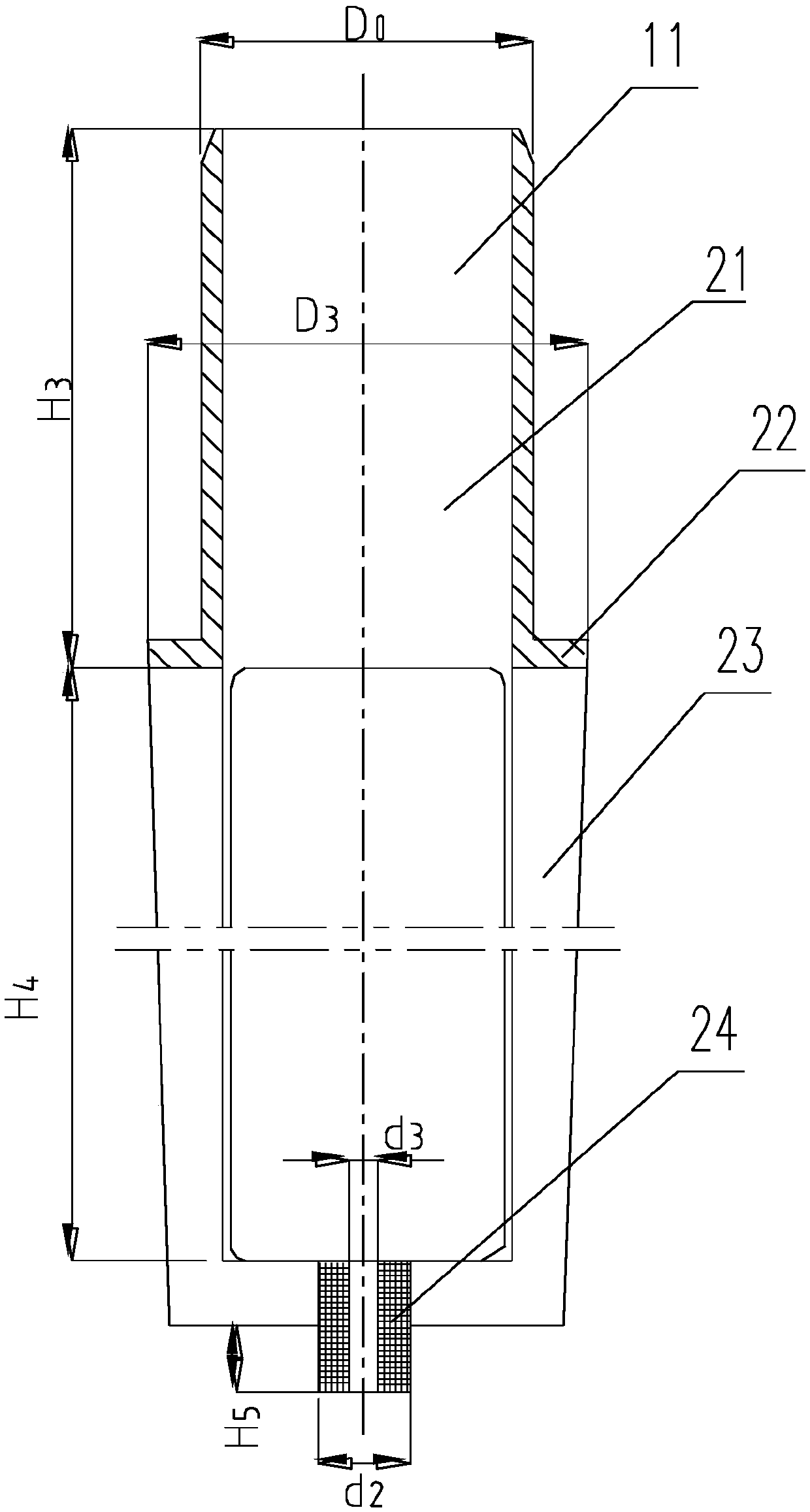
[0013] Attached below figure 1 , figure 2 , image 3 , the present invention is described in further detail.

[0014] In the figure: 1. Evaporation chamber, 2. Super high section, 3. Screen, 4. Sight mirror, 5. Cleaning head, 6. Central circulation pipe, 7. Spiral, 8. Heating pipe, 9. Heating chamber, 10, coupling spring, 11, spring frame, 12, bottom chamber, 13, bottom section, 14, liquid level gauge, 15, top cap, 16, limit hook, 17, straight rib, 18, central axis, 19, oblique Plate tooth, 20, suspension hole, 21, fixed pip...


PUM

PropertyMeasurementUnit
Diameteraaaaaaaaaa
Heightaaaaaaaaaa
Elastic coefficientaaaaaaaaaa

Abstract

The invention discloses a coupling spiral cleaning type natural circulation evaporator. The coupling spiral cleaning type natural circulation evaporator is characterized in that a coupling helix cleaning mechanism composed of cleaning heads, helixes, coupling springs and spring supports is mounted on heating pipes of the natural circulation evaporator. During evaporation production, liquid-vapor two-phase flow at the port section of the heating pipes impacts the cleaning heads to drive the helixes to radially and powerfully vibrate, rotate in 5-20 revolutions per minute and do up-down reciprocating motion in 5-20 times of 30-180 mm per minute so as to effectively and automatically clean salt deposit on the inner walls of the heating pipes. Meanwhile, convection heat transfer of natural circulation liquid flow is enhanced. A forced circulation pump is omitted. The coupling spiral cleaning type natural circulation evaporator is simple in structure and has the automatic cleaning capacityto meet the engineering requirements for long-period continuous and high-efficiency production of the majority of saline solution natural circulation evaporators.

Description

technical field [0001] The invention relates to a coupled spiral cleaning type natural circulation evaporator, which relates to the automatic cleaning and heat transfer enhancement in the heating tube of the natural circulation evaporator. It is mainly suitable for convective heat transfer enhancement and automatic cleaning in the heating tube of high-salt wastewater and inorganic salt solution concentrated crystallization evaporator. Background technique [0002] As we all know, the natural circulation evaporator has the simplest structure, but it cannot be applied to the concentrated crystallization evaporation of high-salt wastewater and inorganic salt solution. Because of the low flow rate of natural circulation, the scaling in the heating tube is faster and thicker than that of other structural types of evaporators, which requires more frequent parking and cleaning, with the lowest efficiency and the highest energy consumption. [0003] Although there have been few lit...

Claims


Application Information

Patent Timeline
IPC IPC(8): F28G9/00F28G15/00
CPCF28G9/00F28G15/00
Inventor 俞天翔张治坤俞天兰俞秀民彭德其吴金香冯修燕
Owner 浙江建装工程技术研究有限公司
Learn More