Automatic blank fetching equipment and method for magnetic material oil hydraulic machine
A material oil and magnetic technology, which is applied in the field of automatic blank picking equipment and blank picking of magnetic material hydraulic presses, can solve the problems of large floor space and inability to realize blank picking and stacking of multi-layer blanks, so as to achieve a small footprint and reduce labor. The effect of taking blanks and not easily damaged
- Summary
- Abstract
- Description
- Claims
- Application Information
AI Technical Summary
Problems solved by technology
Method used
Image
Examples
Embodiment 1
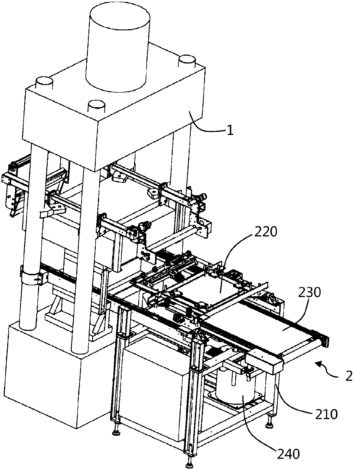
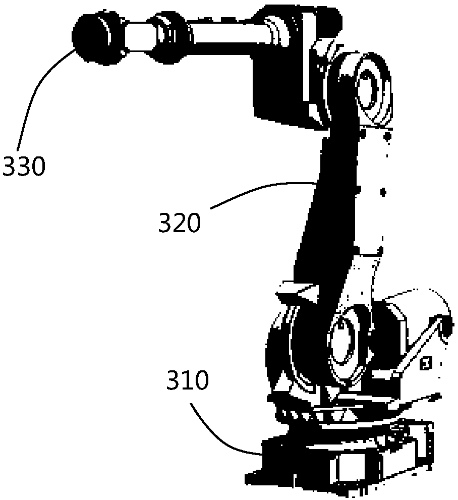
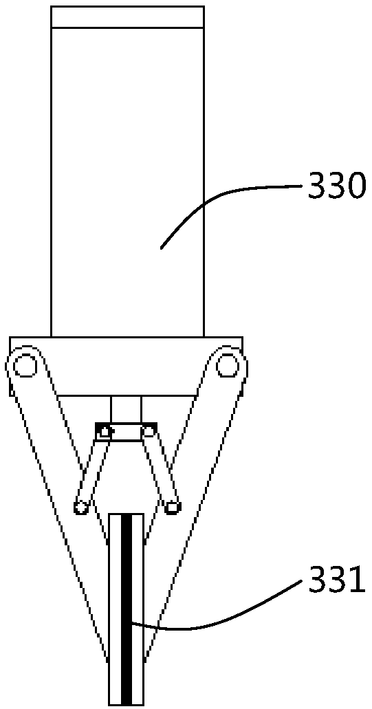
[0047] Magnetic material hydraulic press 1 automatic blanking equipment of the present invention comprises a controller for controlling the whole equipment, a blanking machine 2 arranged on the discharge side of hydraulic press 1 and a blanking machine 2 arranged on any side of said blanking machine 2 ( Both can be on the left side or the right side of the conveyor belt, instead of the front side), the billet removal robot 3 and the billet removal machine 2 are electrically connected to the controller respectively, and the billet removal robot 3 sequentially takes away the codes and places them in the fetching Three-layer magnetically formed blank 6 on blank machine 2. What needs to be explained here is that the magnetic materials involved in the present invention are divided into soft magnetic materials, permanent magnetic materials and functional magnetic materials according to their use, wherein soft magnetic materials and permanent magnetic materials have a wide range of ap...
Embodiment 2
[0053] The basic structure of this embodiment is the same as in Embodiment 1, the difference is: as Figure 4 As shown, the blanking machine 2 also includes a first photoelectric switch 4 and a second photoelectric switch 5, the central axes of the first photoelectric switch 4 and the second photoelectric switch 5 are respectively perpendicular to the central axis of the conveyor belt 230, and the first photoelectric switch 4. Both the second photoelectric switch 5 and the second servo motor are electrically connected to the controller.
[0054] Wherein the motor that drives conveyor belt 230 is the second servo motor, and the second photoelectric switch 5 is arranged on conveyor belt 230 both sides and is apart from conveyor belt 230 head 3-5cm, and optimum value is 4cm, and it should be noted that, the present invention The width of blank is 4cm, because the head of conveyer belt 230 is circular arc shape and the diameter 8-10cm of deflection roller, if blank is conveyed to ...
Embodiment 3
[0057] The basic structure of this embodiment is the same as in Embodiment 2, the difference is that: the lifting mechanism 240 includes a first servo motor, a hydraulic cylinder and a telescopic rod, the first servo motor is electrically connected to the controller, and the telescopic rod is placed in the hydraulic cylinder , the head of the telescopic rod is fixedly connected to the frame 210, and the first servo motor drives the telescopic rod to move and drives the three stations of the frame 210 to move up and down.
[0058] The action of the blank take-off machine 2 will be introduced in detail below: the lifting mechanism 240 drives the conveyor belt 230 to drop the height of a blank, and when the blank take-off suction cup 220 moves the newly obtained blank to the top of the blank that has been placed on the conveyor belt 230 The blanks are released at the same time so that the newly obtained blanks are placed on the blanks that have been placed on the conveyor belt 230...
PUM
 Abstract
Description
Claims
Application Information
 - R&D
- Intellectual Property
- Life Sciences
- Materials
- Tech Scout
- Unparalleled Data Quality
- Higher Quality Content
- 60% Fewer Hallucinations
Browse by: Latest US Patents, China's latest patents, Technical Efficacy Thesaurus, Application Domain, Technology Topic, Popular Technical Reports.
© 2025 PatSnap. All rights reserved.Legal|Privacy policy|Modern Slavery Act Transparency Statement|Sitemap|About US| Contact US: help@patsnap.com


