Chassis device of electric vehicle

A technology for electric vehicles and chassis, applied in electric vehicles, circuits, electrical components, etc., can solve problems such as complex circuits, connection failures, loose bolts, etc., and achieve the effects of optimized circuit structure, high reliability, and simple installation

Pending Publication Date: 2018-02-23
OPTIMUM BATTERY CO LTD
View PDF9 Cites 2 Cited by
  • Summary
  • Abstract
  • Description
  • Claims
  • Application Information

AI Technical Summary

Problems solved by technology

[0003] The connection between the single cells in the existing battery pack is mainly by bolt connection and welding: the operation of bolt connection is complicated, and the contact resistance of the whole battery pack is increased, and some bolts will loosen during vibration, which will lead to connection failure; However, welding requires high technology and high equipment cost, and it is inconvenient to disassemble, assemble and maintain the welded batteries when they fail.
At present, the commonly used battery confluence method mainly uses PCB board or wire confluence, and the internal monitoring module is connected by wire, which makes the overall circuit complex and requires high professionalism for installation and maintenance personnel.

Method used


Image

  • Chassis device of electric vehicle
  • Chassis device of electric vehicle
  • Chassis device of electric vehicle

Examples


Embodiment Construction

[0024] In order to make the object, technical solution and beneficial technical effects of the present invention clearer, the present invention will be further described in detail below in conjunction with the accompanying drawings and specific embodiments. It should be understood that the specific implementations described in this specification are only for explaining the present invention, not for limiting the present invention.

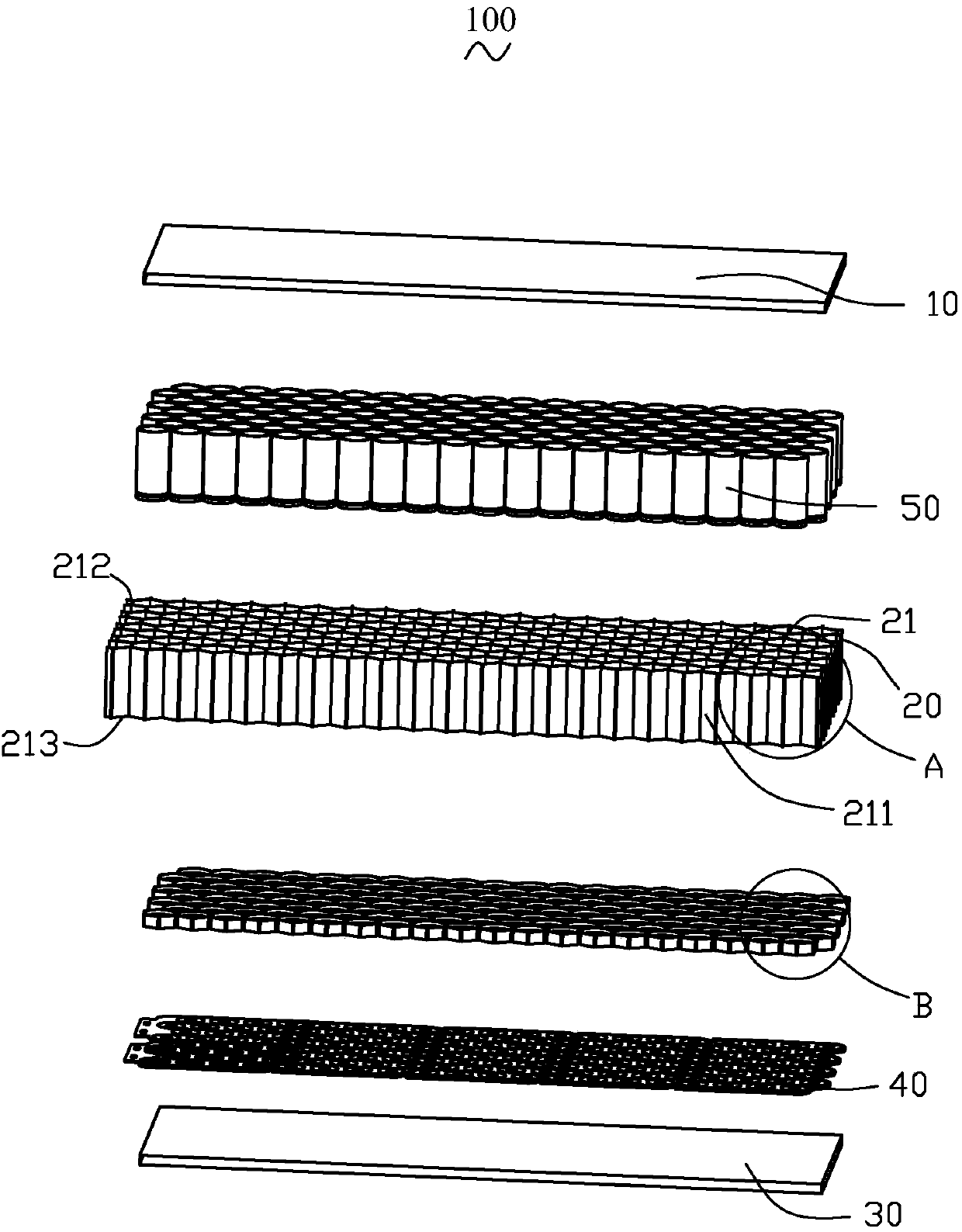
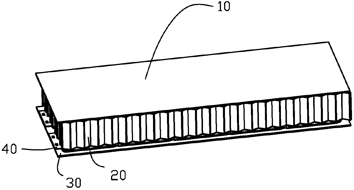
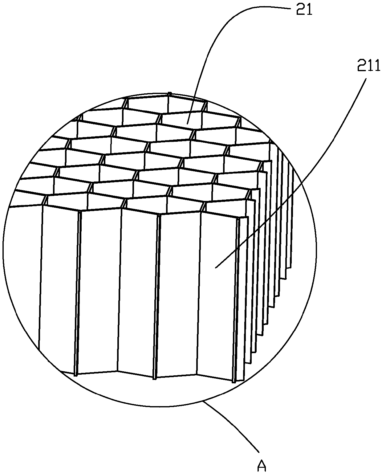
[0025] Such as figure 1 , 2 and Figure 6 As shown, an electric vehicle chassis device 100 provided by the present invention includes an upper cover plate 10 , a honeycomb housing structure 20 , a lower guard plate 30 , a bus circuit board 40 and a plurality of single cells 50 .

[0026] The bus circuit board 40 includes a positive bus layer 41 and a negative bus layer 42 located on the positive bus layer 41 and insulated from the positive bus layer 41 . The bus circuit board 40 is disposed on the lower guard plate 30 , the honeycomb housing str...


PUM

PropertyMeasurementUnit
tensile strengthaaaaaaaaaa
thicknessaaaaaaaaaa

Abstract

Provided is a chassis device of an electric vehicle. The device comprises an upper cover plate, a cellular holding structure, a lower guard board, a bus circuit board, and a plurality of battery cells. The bus circuit board comprises an anode bus layer and a cathode bus layer on the anode bus layer. The bus circuit board is arranged on the lower guard board. The cellular holding structure is arranged on the cathode bus layer. The upper cover plate is arranged on the cellular holding structure. The cellular holding structure comprises a plurality of hollow cell units. Each battery cell includesan anode end and a housing contact ring surrounding the anode end. Each battery cell is held in a corresponding cell unit. The cathode bus layer includes a cathode circuit layer and is provided witha plurality of via holes. Part of the cathode circuit layer is exposed and forms a plurality of cathode contact parts. The anode bus layer includes a plurality of anode contact parts. Each anode contact part is in one corresponding via hole. The housing contact ring of each battery cell is abutted against the corresponding cathode contact part. The anode end of each battery cell is abutted againstthe corresponding anode contact part.

Description

【Technical field】 [0001] The invention relates to the technical field of electric vehicles, in particular to an electric vehicle chassis device. 【Background technique】 [0002] Under the pressure of energy crisis and environmental pollution, safety, environmental protection, and energy saving have become the themes of today's automobile development. Electric vehicles have been highly valued and supported by transportation and energy departments because of their advantages in energy saving, environmental protection, and pollution-free. In recent years, The new energy automobile industry ushered in explosive growth. The battery is the core of electric vehicles, and it is also a comprehensive embodiment of automotive engineering and power engineering technology, and the battery module packaging technology and the confluence between battery cells are also an important part of it. [0003] The connection between the single cells in the existing battery pack is mainly by bolt con...

Claims


Application Information

Patent Timeline
Patent Type & Authority Applications(China)
IPC IPC(8): B60L11/18B62D21/00H01M2/10H01M2/20H01M50/249H01M50/505H01M50/543
CPCB62D21/00B60L50/50H01M50/256H01M50/20H01M50/50Y02T10/70Y02E60/10
Inventor 王敬波王哲段桂林钟河金曾勇帅
Owner OPTIMUM BATTERY CO LTD
Why Eureka
Try Eureka