
A Stereoscopic Fabrication Method Based on Flexible and Deformable Microlens Array

A technology of microlens array and manufacturing method, which is applied in the direction of nanostructure manufacturing, nanotechnology, nanotechnology, etc., can solve the problems of limited 3D printing materials, printing three-dimensional shapes, product manufacturing errors, etc., and achieve simplified process flow, convenient production, The effect of simple process

Active Publication Date: 2019-04-09
XI AN JIAOTONG UNIV
View PDF8 Cites 0 Cited by
  • Summary
  • Abstract
  • Description
  • Claims
  • Application Information

AI Technical Summary

Problems solved by technology

[0002] The traditional 3D printing technology adopts the method of layered manufacturing, which can only be used for surface manufacturing, and cannot realize instant rapid three-dimensional molding. The "step effect" in the process also brings large errors to the manufacturing of products.
At the same time, the available 3D printing materials are limited, most of which are gypsum, inorganic powder, photosensitive resin, plastic and other materials. There is a lack of performance, and it is increasingly unable to adapt to the high requirements of technological development for product functionality.

Method used


Image

  • A Stereoscopic Fabrication Method Based on Flexible and Deformable Microlens Array
  • A Stereoscopic Fabrication Method Based on Flexible and Deformable Microlens Array
  • A Stereoscopic Fabrication Method Based on Flexible and Deformable Microlens Array

Examples


Embodiment Construction

[0024] In order to make the object, technical solution and advantages of the present invention clearer, the present invention will be further described below through the accompanying drawings and embodiments.

[0025] A three-dimensional manufacturing method based on a flexible deformable microlens array, comprising the following steps:

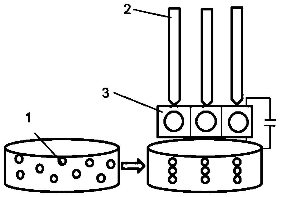
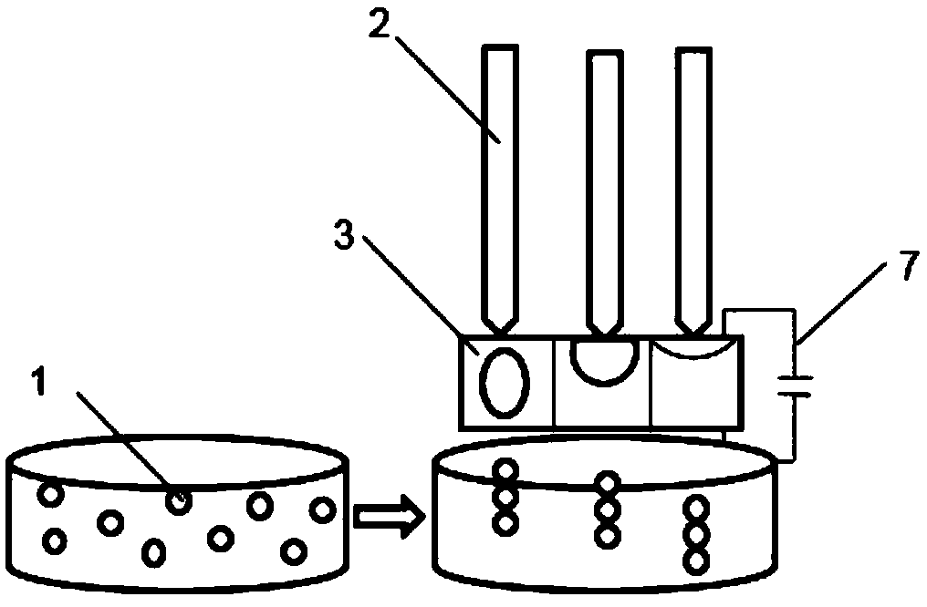
[0026] 1) placing microscopic particles 1 of micro-nano scale in pure water, stirring to make them evenly distributed, and obtaining an aqueous solution containing microscopic particles;

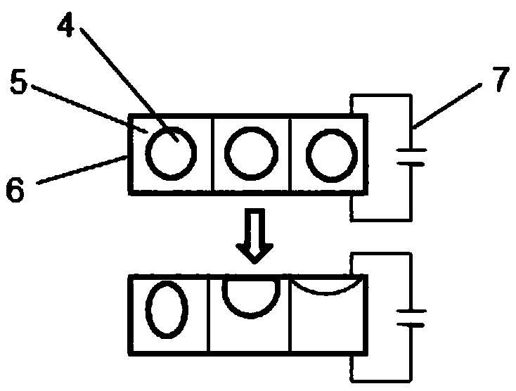
[0027] 2) The light is applied to the microscopic particles 1 through the optical fiber 2 and the flexible deformable microlens array 3. Since the flexible deformable microlens array 3 has a relatively high refractive index, an optical potential well can be formed at its exit end, thereby Microscopic particles 1 in aqueous solution are manipulated, such as figure 1 shown;

[0028] 3) Apply an inhomogeneous external field force to the flexible deformable m...


PUM


Abstract

Provided is a three-dimensional manufacturing method based on a flexible and deformable micro-lens array. The method comprises the steps of: adding microscopic particles into pure water, stirring themixture evenly, and then applying light to the microscopic particles through optical fiber and the flexible and deformable micro-lens array to form an optical potential well at the emitting end of theflexible and deformable micro-lens array so as to achieve control over the microscopic particles in the aqueous solution; then applying an external field force on the flexible and deformable micro-lens array so as to change the spatial pose and radius of curvature of the flexible and deformable micro-lens array so as to achieve control over the microscopic particles on different planes; then changing the power of incident light so as to change the thickness of arrangement of the microscopic particles, which can be controlled every time, in the aqueous solution so as to achieve control over the range of the depth of field in three-dimensional manufacture; and finally performing fixation forming on the accumulated microscopic particles in the aqueous solution so as to achieve manufacture ofa three-dimensional structure. The three-dimensional manufacturing method based on the flexible and deformable micro-lens array has the advantages of being simple in process, large in depth of field,high in efficiency, capable of adjusting time / domain and achieving rapid prototyping and the like.

Description

technical field [0001] The invention belongs to the technical field of optics and micro-nano manufacturing, and in particular relates to a three-dimensional manufacturing method based on a flexible deformable microlens array. Background technique [0002] The traditional 3D printing technology adopts the method of layered manufacturing, which can only be used for surface manufacturing, and cannot realize instantaneous rapid three-dimensional molding. The "step effect" in the process also brings large errors to the manufacturing of products. At the same time, the available 3D printing materials are limited, most of which are gypsum, inorganic powder, photosensitive resin, plastic and other materials. There is a lack of performance, and it is increasingly unable to adapt to the high requirements of technological development for product functionality. [0003] With the development of zoom lens manufacturing technology, zoom lenses are gradually widely used in daily life, such ...

Claims


Application Information

Patent Timeline
Patent Type & Authority Patents(China)
IPC IPC(8): B82B3/00
CPCB82B3/0061
Inventor 王兰兰张雅君刘红忠
Owner XI AN JIAOTONG UNIV
Learn More