Rotary water-distributing type IC anaerobic reactor

An anaerobic reactor and rotary water distribution technology, applied in anaerobic digestion treatment, chemical instruments and methods, biological water/sewage treatment, etc. The effect of saving energy consumption and maintaining activity

Pending Publication Date: 2018-02-23
河南小威环境科技有限公司
View PDF7 Cites 10 Cited by
  • Summary
  • Abstract
  • Description
  • Claims
  • Application Information

AI Technical Summary

Problems solved by technology

In addition, the effluent of the traditional IC anaerobic reactor flows out from the top of the tank and directly flows back to the circulation tank through the pipeline. A large amount of air will be dissolved in the flow process, which is equivalent to increasing the oxygen of the wastewater. The anaerobic bacteria species are very unfavorable, resulting in poor wastewater treatment effect

Method used


Image

  • Rotary water-distributing type IC anaerobic reactor
  • Rotary water-distributing type IC anaerobic reactor
  • Rotary water-distributing type IC anaerobic reactor

Examples


Embodiment 1

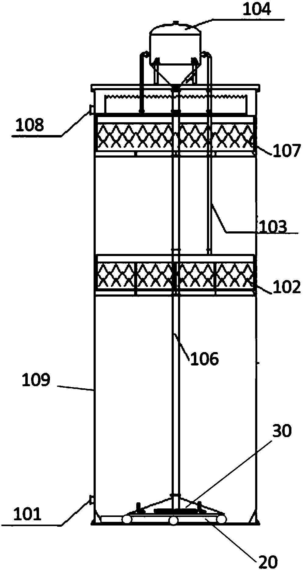
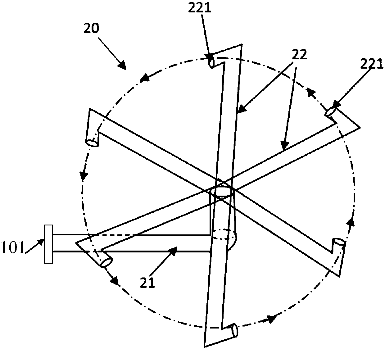
[0047] Such as figure 2 and image 3 Shown, the rotary water distribution type IC anaerobic reactor of an embodiment of the present invention, it comprises: reaction tower 109, and its bottom is provided with water inlet 101, and its top is provided with drain outlet 108, and in reaction tower 109, from bottom to top successively There are water inlet water distribution device 20, return water distribution device 30, internal return pipe 106, first three-phase separator 102, second three-phase separator 107, gas-water separator 104, wherein the upper end of internal return pipe 106 is connected The gas-water separator 104, the lower end of the internal return pipe 106 is towards the bottom of the reaction tower 109; the upper side of the first three-phase separator 102 and the second three-phase separator 107 are respectively connected to a biogas collector Pipe 103, the biogas collection pipe 103 communicates with the gas-water separator 104 above the reaction tower 109. T...

Embodiment 2

[0050] Such as Figure 4 Shown is yet another embodiment of the present invention. The difference between this embodiment and Embodiment 1 is that on the basis of Embodiment 1, the traditional backflow water distribution device 30 is improved, and at the same time, the backflow water distribution device 30 and the inlet water distribution device 20 are synergistic and mutually promoted role.

[0051] See Figure 4 As shown, the return water distribution device 30 has a similar structure to the inflow water distribution device 20 . The return water distribution device 30 is connected to the lower end of the inner return pipe 106 . The backflow water distribution device 30 includes two or more sub-pipes 31 radially arranged, and the sub-pipes are provided with backflow holes 311, wherein the backflow holes 311 all face counterclockwise or all face clockwise , and the direction of the return hole 311 is the same as that of the water inlet hole 221 of the water inlet and distr...

Embodiment 3

[0054] Embodiment 3 is based on Embodiment 1, and does not limit the inlet water distribution device 20, but only improves the return water distribution device 30 as in Embodiment 2, that is, the return water distribution device 30 is connected to the inner return pipe 106 lower end. The backflow water distribution device 30 includes two or more sub-pipes 31 radially arranged, and the sub-pipes are provided with backflow holes 311, wherein the backflow holes 311 all face counterclockwise or all face clockwise .


PUM


Abstract

The invention relates to a rotary water-distributing type IC (internal circulation) anaerobic reactor. The rotary water-distributing type IC anaerobic reactor comprises a reaction tower, wherein the bottom of the reaction tower is provided with a water inlet, a water discharging opening is formed in the upper part of the reaction tower, and a water introducing and distributing device, a reflux water distributing device, an inner reflux pipe, a first three-phase separator, a second three-phase separator and a gas-water separator are arranged in the reaction tower from bottom to top sequentially; the upper end of the inner reflux pipe communicates with the gas-water separator, and the lower end of the inner reflux pipe is arranged towards the bottom of the reaction tower; the upper part of the first three-phase separator and the upper part of the second three-phase separator are each connected with a biogas collecting pipe which communicates with the gas-water separator, and the water inlet is connected with the water introducing and distributing device which comprises a main connecting pipe; and one end of the main connecting pipe is provided with two or more branch pipes which areradially arranged, each branch pipe is provided with a water inlet hole, and the water inlet holes all face to the counter-clockwise direction or the clockwise direction. In the way, sewage which is injected into the water inlet can be mixed with anaerobic bacteria-containing sludge in the tower evenly, so that the effect of mass transfer between the sewage and anaerobic bacteria is improved.

Description

technical field [0001] The invention relates to an IC anaerobic reactor, in particular to a rotary water distribution type IC anaerobic reactor. Background technique [0002] IC (internal circulation) reactor is a new generation of high-efficiency anaerobic reactor, that is, internal circulation anaerobic reactor, which is basically composed of two layers of UASB reactors connected in series, and is used for organic high-concentration wastewater, such as corn starch wastewater, lemon Acid wastewater, beer wastewater, potato processing wastewater, alcohol wastewater. UASB is the English abbreviation of (Up-flow Anaerobic Sludge Bed / Blanket), which is an upflow anaerobic sludge bed reactor, which is an anaerobic biological method for sewage treatment, also called upflow anaerobic sludge bed . The IC reactor consists of upper and lower reaction chambers. Wastewater flows from bottom to top in the reactor, pollutants are adsorbed and degraded by bacteria, and purified water f...

Claims


Application Information

Patent Timeline
Patent Type & Authority Applications(China)
IPC IPC(8): C02F3/28
CPCC02F3/2873C02F2203/006
Inventor 郎学芳顾琰
Owner 河南小威环境科技有限公司
Why Eureka
Try Eureka