Rotating RTO

A rotary valve, regenerator technology, applied in rotary RTO. It can solve the problems of pressure pulse and fluctuation, poor energy saving and environmental protection benefits, and low treatment efficiency, and achieve the effects of stable exhaust concentration, fewer use failures, and high treatment efficiency.

Inactive Publication Date: 2018-02-23
JIANGSU BAI NA ENVIRONMENTAL PROTECTION EQUIPCO
View PDF7 Cites 5 Cited by
  • Summary
  • Abstract
  • Description
  • Claims
  • Application Information

AI Technical Summary

Problems solved by technology

[0003] The purpose of the present invention is to provide a rotary RTO to solve the problems of large operation and high maintenance cost, low processing efficiency, high failure rate, pressure pulse and fluctuation when the valve is switched, and poor energy saving and environmental protection benefits

Method used


Image

  • Rotating RTO
  • Rotating RTO

Examples


Embodiment Construction

[0014] The technical solutions in the embodiments of the present invention will be clearly and completely described below in conjunction with the accompanying drawings in the embodiments of the present invention. Obviously, the described embodiments are only a part of the embodiments of the present invention, rather than all the embodiments. Based on the embodiments of the present invention, all other embodiments obtained by those of ordinary skill in the art without creative work shall fall within the protection scope of the present invention.

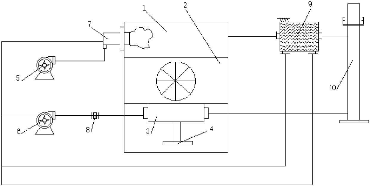
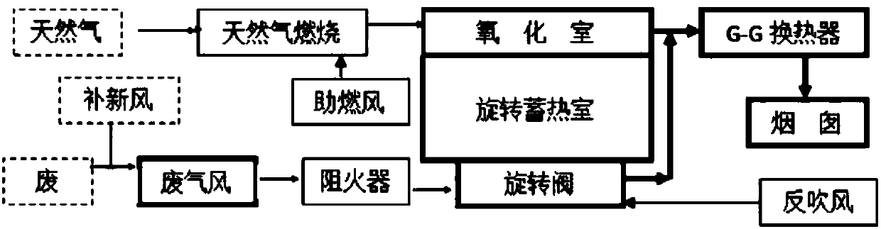
[0015] See Figure 1-2 , The present invention provides a technical solution: a rotary RTO comprising a thermal oxidation chamber 1, a rotary regenerator 2, a rotary valve 3, a motor 4, an oxygen supplement fan 5, an exhaust gas fan 6, a combustion-supporting burner 7, and a flame arrestor 8. , GG heat exchanger 9, and chimney 10. The lower part of the thermal oxidation chamber 1 is provided with a rotary regenerator 2 to preheat the exh...


PUM


Abstract

The invention discloses a rotating RTO. The rotating RTO comprises a thermal oxidation chamber, a rotating regenerative chamber, a rotating valve, a motor, an oxygen supplementing draught fan, an exhaust gas fan, a combustion-supporting burner, a flame arrester, a G-G heat exchanger and a chimney; the rotating regenerative chamber is arranged on the lower portion of the thermal oxidation chamber;the rotating valve is arranged on the lower portion of the rotating regenerative chamber; the motor is arranged on the lower portion of the rotating valve; the flame arrester is arranged on the left side of the rotating valve; the exhaust gas fan is arranged on the left side of the flame arrester; the oxygen supplementing draught fan is arranged on the upper portion of the exhaust gas fan; the combustion-supporting burner is arranged on the right side of the oxygen supplementing draught fan; the G-G heat exchanger is arranged on the right side of the thermal oxidation chamber; and the chimneyis arranged on the right side of the G-G heat exchanger; heat of a combustion chamber is fully utilized, on one hand, the heat is transmitted to a heat accumulator to preheat exhaust gas, and the heatefficiency is improved; and on the other hand, after high temperature flue gas and low temperature flue gas going out because of heat release of the regenerative chamber are mixed, mixed gas enters the G-G heat exchanger, hot air is recycled, the dual effects of energy conservation and environment protection are achieved, and the exhaust gas treatment efficiency reaches 99%.

Description

Technical field [0001] The invention relates to the technical field of environmental protection, in particular to a rotary RTO. Background technique [0002] In today's society, waste gas pollution is serious, and effective treatment of waste gas has become the top priority of the environmental protection industry. As one of the important methods of organic waste gas treatment, the incineration method has high treatment efficiency, but it covers a large area, large investment, safe operation, and high technical requirements. Therefore, how to maintain the advantages, improve and overcome the shortcomings, this requires us to discuss in depth One thing. Summary of the invention [0003] The purpose of the present invention is to provide a rotary RTO to solve the problems of large operation and high maintenance cost, low processing efficiency, high failure rate, pressure pulses and fluctuations during valve switching, and poor energy saving and environmental protection benefits. [...

Claims


Application Information

Patent Timeline
Patent Type & Authority Applications(China)
IPC IPC(8): F23G7/06F23G5/46
CPCF23G7/068F23G5/46
Inventor 蔡长根许镇平苏军
Owner JIANGSU BAI NA ENVIRONMENTAL PROTECTION EQUIPCO
Why Eureka
Try Eureka