
Signal processing system for removing OTDR noise

A signal processing and noise technology, applied in transmission systems, electromagnetic wave transmission systems, electromagnetic transmitters, etc., can solve problems such as inherent noise differences, and achieve the effect of suppressing noise, improving signal-to-noise ratio, and improving suppression effect.

Active Publication Date: 2018-02-27
GUANGXUN SCI & TECH WUHAN
View PDF3 Cites 7 Cited by
  • Summary
  • Abstract
  • Description
  • Claims
  • Application Information

AI Technical Summary

Problems solved by technology

In the figure, after the a pulse is sent, the received data series obtains the data sequence SER1, after the b pulse is sent, the accumulator obtains the result SER1, the received data series obtains the data sequence SER2, and after the c pulse is sent, the accumulator obtains the result SER1#SER2 , the received data series obtains the data sequence SER3, after the d pulse is sent out, the accumulator obtains the result SER1#SER2#SER3, the received data series obtains the data sequence SER4, and so on, after all the q pulses are sent out, the accumulator obtains the result SER1# SER2#SER3#...#SER(q-1), the received data series obtains the data sequence SERq, and in the next clock cycle, no more pulses are sent, and the accumulator obtains the result SER1#SER2#SER3#...#SER (q-1)#SERq, it is easy to notice that OTDR is an application that obtains high signal-to-noise ratio and long measurement time through repetitive measurement. Then, for the interference of non-stationary noise sources, such as instantaneous impact, short-term Noise sources such as temperature changes, occasional device failure or abnormal operation, etc. have not been dealt with in a targeted manner
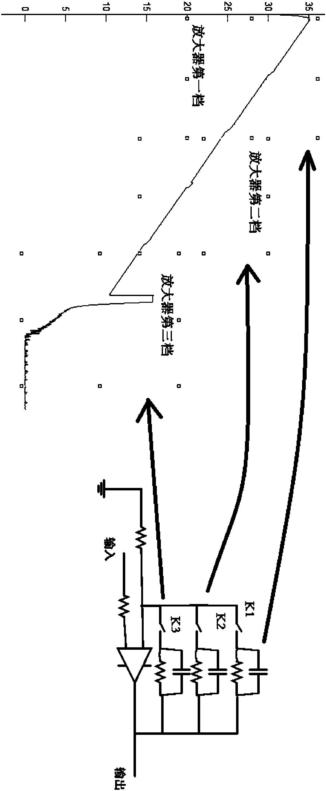
[0005] Additionally, if image 3 As shown, in order to obtain the return light signal sequence with a large dynamic range while ensuring the detection linearity, the existing conventional method is to use a linear circuit with a shifting structure. image 3 The circuit structure on the right side shows that when working, depending on the required detection range, only K1 (that is, the path), only K2 (that is, the path), and only K3 (that is the path) are turned on to obtain different magnifications. measurement to ensure a large dynamic range measurement, corresponding to image 3 The test curve of the OTDR is actually obtained on the left side. The first gear part of the marker amplifier is the measurement result of the K1 channel, the second gear part of the marker amplifier is the measurement result of the K2 channel, and the third gear part of the marker amplifier is the measurement result of the K3 channel. Due to different Gear circuits essentially have different frequency response ranges, and their inherent noises are also different, which is also a typical non-stationary noise source

Method used


Image

  • Signal processing system for removing OTDR noise
  • Signal processing system for removing OTDR noise
  • Signal processing system for removing OTDR noise

Examples


Embodiment Construction

[0041] In order to facilitate those of ordinary skill in the art to understand and implement the present invention, the present invention will be further described in detail below with reference to the accompanying drawings and specific embodiments.

[0042] The present invention provides a digital signal processing system capable of processing noise in OTDR, especially non-stationary noise, and its system framework is as Figure 4 Shown, including analog-to-digital converter ADC, laser and drive unit, sequence accumulator, preprocessing counter, pulse generator, dual-port memory (ie preprocessing data memory), adaptive filter, event arbiter, preprocessing data The arbiter, interrupt service routine and other parts, including:

[0043] The pulse generator includes a digital circuit for generating electrical pulses, and the generated electrical pulses correspond to the required light pulses with a certain measured pulse width. The measured pulse width is usually specified by a user ...


PUM


Abstract

The invention relates to a signal processing system for removing OTDR noise. The signal processing system comprises an analog-to-digital converter, a laser, a driving unit, a sequence accumulator, a preprocessing counter, a pulse generator, a dual-port memory, an adaptive filter, an event decision device and a preprocessed data decision device. The adaptive filter reads preprocessed data from a read-only port of the dual-port memory, and performs noise processing on the read preprocessed data by using an adaptive filtering method of wavelet transform; the event decision device performs event decision on the filtered data output from the adaptive filter; and the preprocessed data decision device decides whether a certain group of preprocessed data in m groups of preprocessed data is correctdata or high-signal-to-noise data according to the difference of the m groups of preprocessed data subjected to the processing of the event decision device.

Description

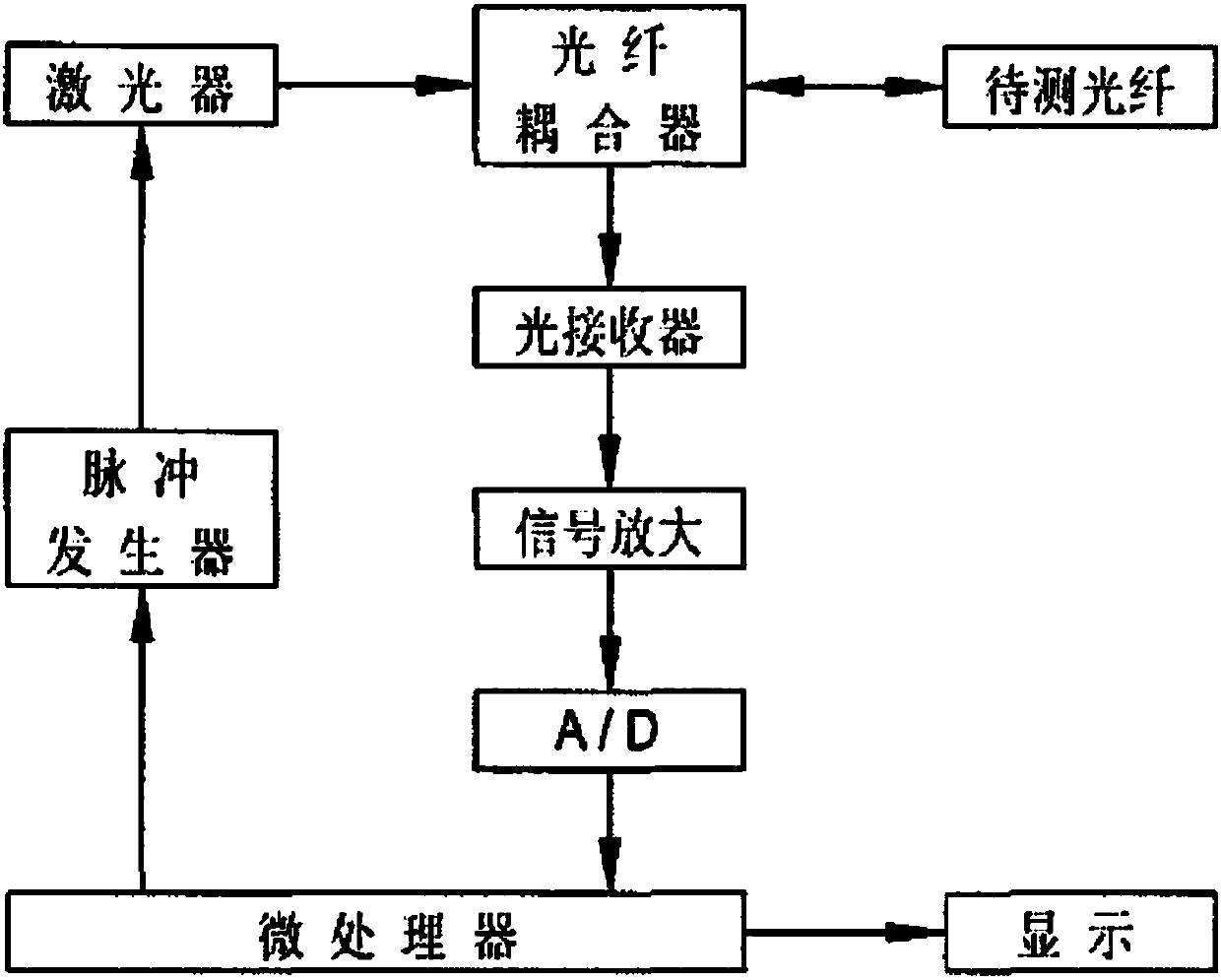
Technical field [0001] The invention relates to a signal processing system, in particular to a signal processing system for removing noise applied to an OTDR, and is particularly suitable for removing non-stationary noise of an OTDR. Background technique [0002] Conventionally, the composition of an optical time domain reflectometer (OTDR) device is as follows figure 1 As shown, the classic description of the working process of the OTDR is as follows: each time a test, the microprocessor sends a command to the pulse generator, the pulse generator sends out electrical pulses, and the laser is controlled by the electrical pulses to generate light pulses with a narrow width. The fiber coupler is injected into the fiber under test, and the light pulse propagates in the fiber, and the backscattered light from various points along the fiber returns to the injection end of the fiber, and then is reflected to the light receiver through the fiber coupler. The role of the optical receiver...

Claims


Application Information

Patent Timeline
Patent Type & Authority Applications(China)
IPC IPC(8): H04B10/071H04B10/079H04B10/50H04B10/69
CPCH04B10/071H04B10/0795H04B10/503H04B10/697H04B10/07953
Inventor 张鹏张建涛张翠红
Owner GUANGXUN SCI & TECH WUHAN
Learn More