Suspension type water wheel low water head tail water power generation system

A power generation system, low water head technology, applied in hydroelectric power generation, hydropower stations, reaction engines, etc., to achieve high efficiency

Pending Publication Date: 2018-03-02
顾坚毅 +1
View PDF0 Cites 3 Cited by
  • Summary
  • Abstract
  • Description
  • Claims
  • Application Information

AI Technical Summary

Problems solved by technology

[0005] The purpose of the present invention is to propose a suspended water wheel low head tail water power generation system that adapts to the characteristics of the tail water fluid of the dam power station and can adjust the water flow

Method used


Image

  • Suspension type water wheel low water head tail water power generation system
  • Suspension type water wheel low water head tail water power generation system
  • Suspension type water wheel low water head tail water power generation system

Examples


Embodiment 1

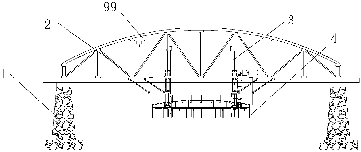
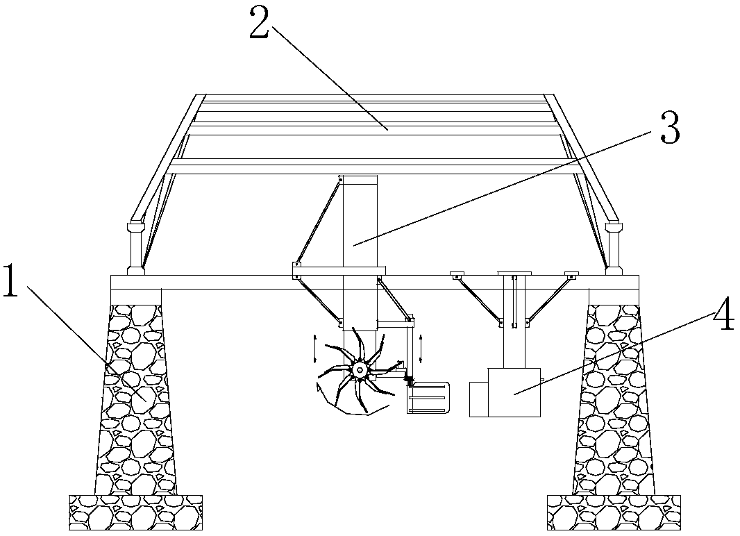
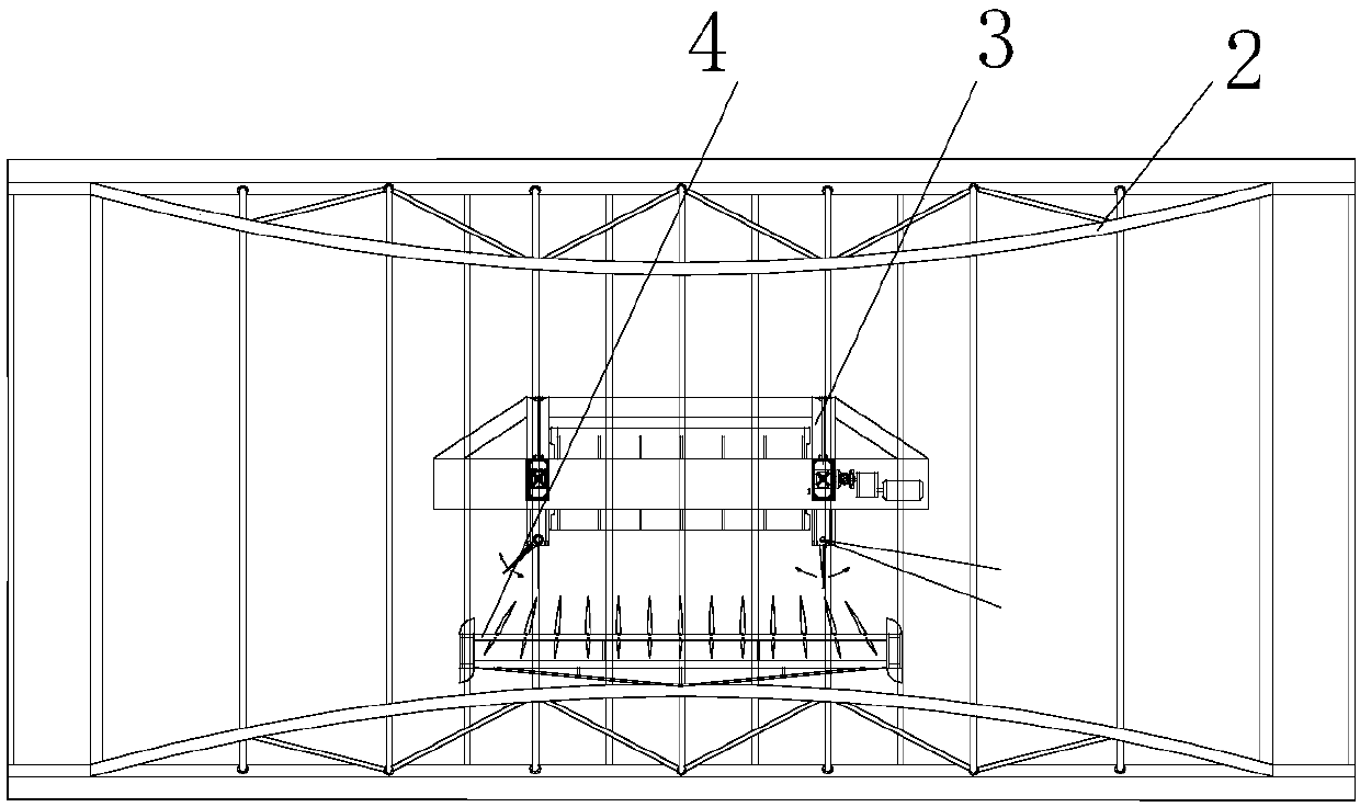
[0069] The suspended water wheel low water head tail water power generation system of this embodiment has a structure such as Figure 1 to Figure 3 As shown, it includes four reinforced concrete support columns 1, and the support columns 1 are symmetrically arranged on both sides of the tailrace (built on both sides of the tailrace or in the tailrace, and the two supporting columns 1 facing the water are built in the tailrace) In the middle, the two face the direction of the water flow in the shape of a bell mouth, so as to play the role of guiding and expanding the storage of incoming water, enhance the flow velocity, and increase the water energy). Conditions such as water depth and generator set hanging water wheels are determined. The lower end of the supporting column 1 is connected with the foundation, and the upper end is connected with the steel truss bearing beam 2 for supporting the steel truss bearing beam 2 . The inner side of the upper part of the steel truss bea...

Embodiment 2

[0079] The difference between this embodiment and Embodiment 1 is that the structures of the left and right flow regulators are inconsistent, the left flow regulator is an electric regulating flow regulator, and the right flow regulator is a mechanical regulating flow regulator. The relationship between the two is , with mechanical adjustment as the main adjustment, and electric adjustment as compensation fine-tuning (see Figure 7 ). The structure of the electrically adjustable flow regulator is detailed in Embodiment 1.

[0080] The structure of the mechanically regulated flow regulator is as follows: Figure 7 and Figure 32 shown. The upper and lower movable pull rods are keytooth-shaped up and down movable pull rods 87, and the top of the keytooth-shaped up and down movable pull rods 87 is a keytooth-shaped structure, the middle and lower parts are cylindrical structures with different diameters, and the lower end is a screw structure with external threads. The bottom...

Embodiment 3

[0088] The difference between this embodiment and Embodiment 1 is that a right flow regulator is installed at the bottom of the right movable cantilever 22, and no flow regulator is placed under the left movable cantilever 17; the right flow regulator is a mechanically regulated flow regulator .

[0089] The suspension type water wheel low water head tail water power generation system of the present invention, economically speaking, the tail water power station fully utilizes the water source accumulation resources and excellent water quality resources formed by the huge investment of the previous dam power station (after the previous dam power station) Filtration), tail water channel resources, power grid power transmission and transformation resources, transportation and living service resources, resettlement demolition resources and a series of favorable resources, relying on the secondary power generation of the dam tail water, almost only requires direct equipment investme...


PUM


Abstract

The invention relates to a suspension type water wheel low water head tail water power generation system which comprises a supporting column. A steel truss bearing beam is installed on the top of thesupporting column, an equipment base plate is installed at the bottom of the steel truss bearing beam and provided with a power generator set, the power generator set comprises a gear box, a power generator, a fixed suspension arm, a movable suspension arm and the like. A water wheel assembly is connected to the movable suspension arm in a downward suspension mode, a floating type flow guide waterlattice is arranged in front of the upstream face of the water wheel assembly, the portion, facing water flow, of the movable suspension arm is provided with a flow adjuster, the flow adjuster comprises an upper arm, a lower arm, an up-down movement pull rod and a flow adjusting plate. The suspension type water wheel low water head tail water power generation system has the advantages that the suspension type water wheel design is adopted, and therefore the system can adapt to dam type hydropower station tail water channel environments or other complex river bed environments; by means of thespecially-designed novel water wheel assembly and water lattice, water energy can be sufficiently collected and converted into mechanical energy and electric energy; by means of the specially-designedway of combining rotating speed mechanical automatic adjustment and electric adjustment, the tail water flow speed and flow capacity can be effectively controlled, and therefore the rated rotating speed of the power generator is ensured.

Description

technical field [0001] The invention relates to a power generation system, in particular to a suspended water wheel low head tail water power generation system, which belongs to the technical field of hydropower generation. Background technique [0002] my country's natural geography is high in the west and low in the east, and the rivers and rivers stretch for thousands of miles among the high mountains, with a huge drop, and have extremely rich water resources. Vigorously developing green, environmentally friendly and renewable energy is an energy strategy that the state attaches great importance to and actively supports. The country attaches great importance to hydropower construction. In recent decades, more than 46,700 dam-type hydropower stations of different sizes have been built. However, the negative effect of the dam-type power station is that it seriously affects the original natural ecological environment. Objectively speaking, the currently available site sele...

Claims


Application Information

Patent Timeline
Patent Type & Authority Applications(China)
IPC IPC(8): F03B13/00F03B3/12F03B3/18F03B15/08E02B9/00H02K7/18
CPCE02B9/00F03B3/12F03B3/121F03B3/183F03B13/00F03B15/08H02K7/1823Y02E10/20
Inventor 顾坚毅顾云骥
Owner 顾坚毅
Why Eureka
Try Eureka