Drying kiln for ceramic products

A ceramic product and drying kiln technology, which is applied in the direction of ceramic product drying, drying, drying machine, etc., can solve the problems of difficult heat circulation in the drying kiln, drying dead angle, firing failure, etc., to improve the success of drying rate, speed up the drying process, and reduce the effect of residual speed

Inactive Publication Date: 2018-03-02
耒阳市井阳陶瓷有限公司
View PDF0 Cites 7 Cited by
  • Summary
  • Abstract
  • Description
  • Claims
  • Application Information

AI Technical Summary

Problems solved by technology

[0002] Ceramic drying technology generally adopts hot air drying technology. There are three ways of energy sources: natural gas combustion, coal combustion and electric furnace. Sintering, heat preservation, cooling, and final molding, the traditional ceramic drying equipment has a long drying time and low efficiency, and the yield is not high, so now most of them use electric furnace kiln for drying process
However, the current electric furnace kiln produces heat and cools down too fast, and it is easy to have dead angles in the drying process, so that the yield is not high, and the heat in the drying kiln body is difficult to circulate, which will cause color difference in ceramics; in addition , the temperature required for ceramic drying is about 1300 degrees, and the temperature of the drying kiln body is very high during work. It is easy for the staff to grasp the temperature poorly, resulting in firing failure; After drying, a large amount of waste heat will be generated. Most of the existing drying kilns discharge these waste heat into the atmosphere, which will cause waste of resources, which is not environmentally friendly and causes environmental pollution. Therefore, a kind of waste heat is designed and produced. Convenient and practical, energy-saving and environment-friendly ceramic products drying kiln is very necessary

Method used


Image

  • Drying kiln for ceramic products

Examples


Embodiment Construction

[0011] The following will clearly and completely describe the technical solutions in the embodiments of the present invention with reference to the accompanying drawings in the embodiments of the present invention. Obviously, the described embodiments are only some, not all, embodiments of the present invention. Based on the embodiments of the present invention, all other embodiments obtained by persons of ordinary skill in the art without making creative efforts belong to the protection scope of the present invention.

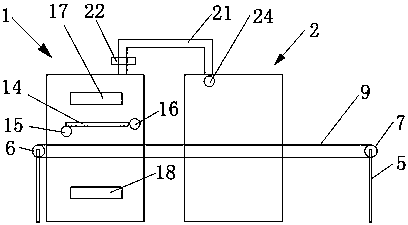
[0012] The present invention provides such figure 1 A kind of ceramic product drying kiln shown, comprises drying room 1, pre-drying room 2, conveying device 23 and control device 20, and described conveying device 23 passes through drying chamber 1 and pre-drying room 2, and described conveying Device 23 comprises drive wheel 6, driven wheel 7, conveyor chain 9, motor 8, first support 4 and second support 5, and described drive wheel 6 and driven wheel 7 are ...


PUM


Abstract

The invention discloses a drying kiln for ceramic products, which comprises a drying chamber, a drying preparation chamber, a transmission device and a control device, the transmission device passes through the drying chamber and the preparation drying chamber, and a partition is arranged in the drying chamber , a first heating box is arranged above the partition, a first exhaust fan is arranged on the right side of the partition, the first storage rack is located below the partition, and a second heating box is arranged below the first storage rack , a blower is provided on the left side of the first shelf, a temperature sensor is provided in the drying chamber, and a communicating pipe is provided at the upper end of the drying chamber. The other end of the connecting pipe is connected to the upper end of the dry room, the port of the connecting pipe is provided with a second exhaust fan, and the connecting pipe is provided with a valve, through which the drying program can be preheated and discharged into the dry room after the drying process is completed. The oven can effectively reduce the drying time of the drying room. The temperature sensor can monitor the temperature of the drying room. Through the regulation of the control device, the temperature of the drying room is closest to the optimal drying temperature.

Description

technical field [0001] The invention belongs to the technical field of drying equipment, and in particular relates to a drying kiln for ceramic products. Background technique [0002] Ceramic drying technology generally adopts hot air drying technology. There are three ways of energy sources: natural gas combustion, coal combustion and electric furnace. Sintering, heat preservation, cooling, and final molding, the traditional ceramic drying equipment has a long drying time and low efficiency, and the yield of finished products is not high, so most of them now use electric furnaces for drying. However, the current electric furnace kiln produces heat and cools down too fast, and it is easy to have dead angles in the drying process, so that the yield is not high, and the heat in the drying kiln body is difficult to circulate, which will cause color difference in ceramics; in addition , the temperature required for ceramic drying is about 1300 degrees, and the temperature of th...

Claims


Application Information

Patent Timeline
Patent Type & Authority Applications(China)
IPC IPC(8): F26B15/18F26B21/00F26B25/08
CPCF26B15/18F26B21/00F26B25/08F26B2210/02
Inventor 曹梦林
Owner 耒阳市井阳陶瓷有限公司
Why Eureka
Try Eureka