Wood drying device utilizing photo-thermal energy

A technology of wood drying and thermal energy, which is applied in the directions of wood drying, static material dryer, heating to dry solid materials, etc. It can solve the problems of low temperature in the glass room, easy radiation loss, and slow drying speed, etc., and achieve good adjustment of light, Good heat preservation and easy drying effect

Inactive Publication Date: 2018-03-06
WUXI ZHIGURUITUO TECH SERVICE CO LTD
View PDF0 Cites 3 Cited by
  • Summary
  • Abstract
  • Description
  • Claims
  • Application Information

AI Technical Summary

Problems solved by technology

[0003] Ordinary wood drying methods include drying in the shade, which takes a long time; artificial heating and drying waste a lot of electric energy, and the ordinary drying device using solar energy through the glass room has a slow drying speed. After the heat is converted, it is easy to be lost by radiation. lower temperature, slower drying

Method used


Image

  • Wood drying device utilizing photo-thermal energy
  • Wood drying device utilizing photo-thermal energy
  • Wood drying device utilizing photo-thermal energy

Examples


Embodiment 1

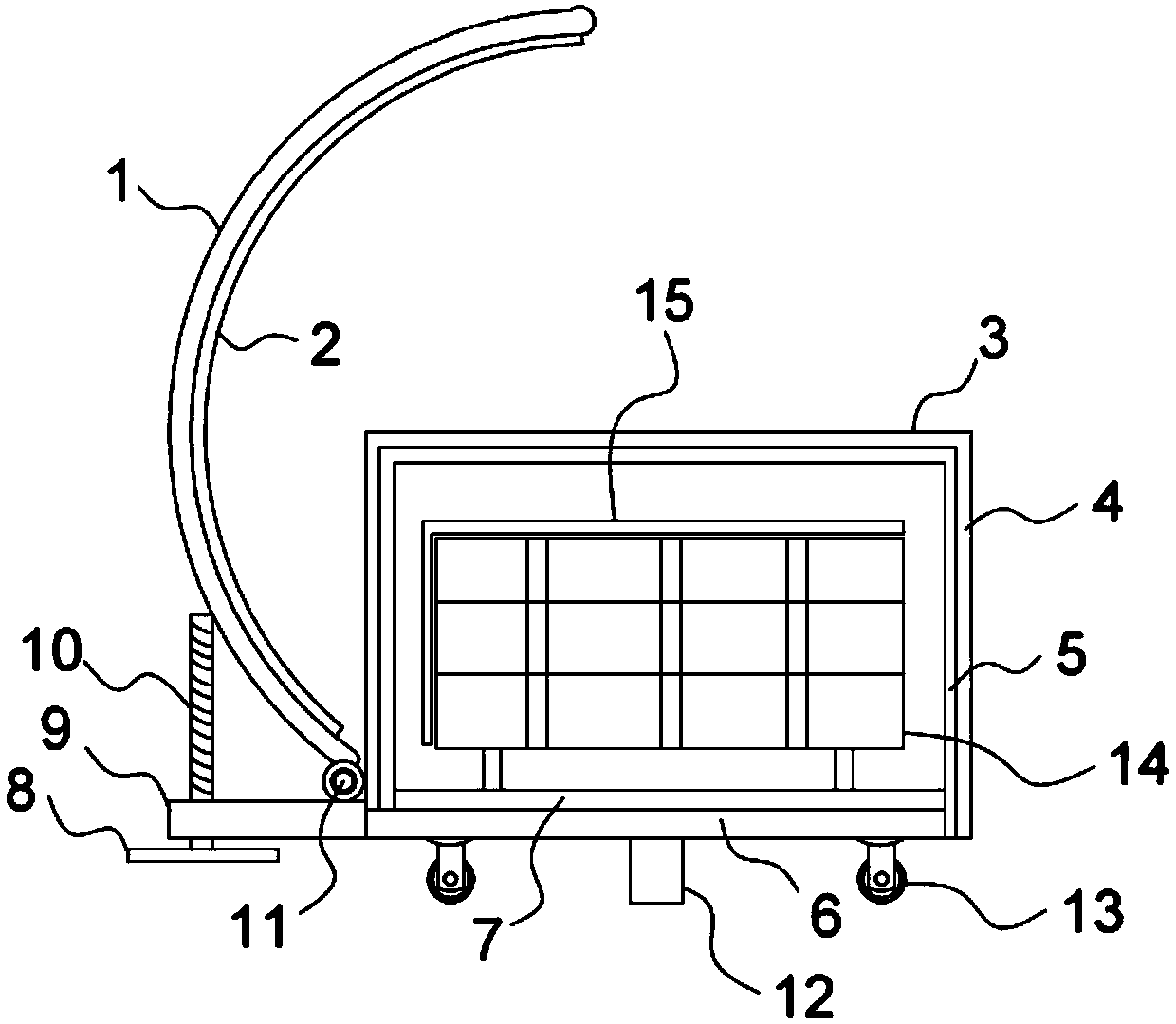
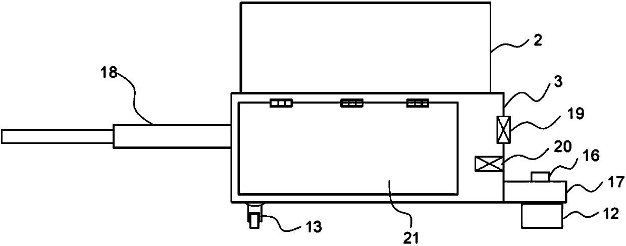
[0031] A wood drying device using light and heat energy, comprising: a transparent glass room 3, which is fixedly installed on a vehicle frame 6, and a support plate 9 is fixedly connected to one side of the vehicle frame 6; an arc-shaped support frame 1, the bottom of which passes through The hinge 11 is hingedly installed on the support plate 9, and one side of the arc support frame 1 is fixedly connected with the arc mirror 2; the screw rod 10 is threaded on the support plate 9 to adjust the height and support the arc support frame The screw rod 10 of 1, the lower end of the screw rod 10 is fixedly connected with the flywheel 8; the timber frame 14, the timber frame 14 is arranged in the transparent glass room 3, and the top of the timber frame 14 is fixedly connected with the sun visor 15; the transparent An internal circulation fan 20 is installed inside the glass house 3 , and a ventilation fan 19 is installed on one side of the transparent glass house 3 , and a transpare...

Embodiment 2

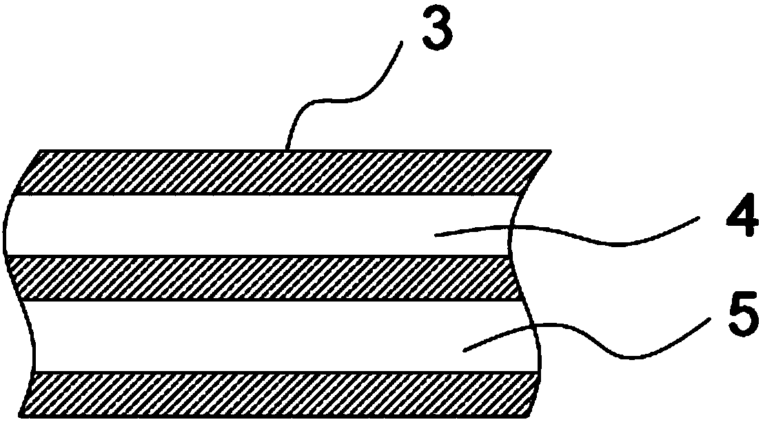
[0034] Different from Embodiment 1, the gases used in the greenhouse gas layer 5 are different, and the details are as follows:

[0035] A wood drying device using light and heat energy, comprising: a transparent glass room 3, which is fixedly installed on a vehicle frame 6, and a support plate 9 is fixedly connected to one side of the vehicle frame 6; an arc-shaped support frame 1, the bottom of which passes through The hinge 11 is hingedly installed on the support plate 9, and one side of the arc support frame 1 is fixedly connected with the arc mirror 2; the screw rod 10 is threaded on the support plate 9 to adjust the height and support the arc support frame The screw rod 10 of 1, the lower end of the screw rod 10 is fixedly connected with the flywheel 8; the timber frame 14, the timber frame 14 is arranged in the transparent glass room 3, and the top of the timber frame 14 is fixedly connected with the sun visor 15; the transparent An internal circulation fan 20 is instal...

Embodiment 3

[0038] The difference from Example 1 is that the charcoal layer 7 is replaced by a moisture-absorbing and heating fiber layer, and the specific content is as follows:

[0039] A wood drying device using light and heat energy, comprising: a transparent glass room 3, which is fixedly installed on a vehicle frame 6, and a support plate 9 is fixedly connected to one side of the vehicle frame 6; an arc-shaped support frame 1, the bottom of which passes through Hinge 11 is hingedly installed on support plate 9, and one side of arc support frame 1 is fixedly connected with arc mirror 2; The screw rod 10 of 1, the lower end of the screw rod 10 is fixedly connected with the flywheel 8; the timber frame 14, the timber frame 14 is arranged in the transparent glass room 3, and the top of the timber frame 14 is fixedly connected with the sun visor 15; the transparent An internal circulation fan 20 is installed inside the glass house 3 , and a ventilation fan 19 is installed on one side of ...


PUM


Abstract

The invention discloses a wood drying device utilizing photo-thermal energy. The wood drying device comprises a transparent glass room, an arc-shaped supporting frame, a threaded rod and a wood frame;the transparent glass room is fixedly arranged on a vehicle frame; an arc-shaped mirror surface is fixedly connected to one side of the arc-shaped supporting frame; the top of the wood frame is fixedly connected with a sun shield; and the side surface of the transparent glass room is provided with a transparent glass door. According to the wood drying device, the arc-shaped mirror surface structure and the threaded rod adjusting structure are arranged so that the light can be better adjusted, and more light and heat energy can be received by the transparent glass room; through the arrangementof a vacuum layer and a greenhouse gas layer, and after the short wave of solar radiation is converted into heat energy, the long wave of the heat energy can be prevented from radiating outwards, sothat the heat can be well stored, and drying can be facilitated; the sun shield is arranged so that the wood can be prevented from directly receiving the light, and the light energy can be fully absorbed to transformed into heat; and the device is simple in structure, easy to realize, capable of fully utilizing the solar energy for achieving the drying function, is environment-friendly and energy-saving, and is worthy of popularization and use.

Description

technical field [0001] The invention belongs to the technical field of wood drying, and more specifically relates to a wood drying device utilizing light and heat energy. Background technique [0002] Wood drying is the process of reducing the moisture content of wood to the applicable value by heating and using the pressure difference of water vapor inside and outside the wood. It is an indispensable production link in the wood industry. The role of wood drying is to reduce weight, save labor and cost of transportation; prevent moth and corrosion, prolong the service life; prevent deformation and warping, increase elasticity, and help improve the quality of wood products. [0003] Ordinary wood drying methods include drying in the shade, which takes a long time; artificial heating and drying waste a lot of electric energy, and the ordinary drying device using solar energy through the glass room has a slow drying speed. After the heat is converted, it is easy to be lost by r...

Claims


Application Information

Patent Timeline
Patent Type & Authority Applications(China)
IPC IPC(8): F26B3/28F26B9/02F26B25/06
CPCF26B3/286F26B9/02F26B25/06F26B2210/16
Inventor 不公告发明人
Owner WUXI ZHIGURUITUO TECH SERVICE CO LTD
Why Eureka
Try Eureka