Microdosing device and automatic microdosing method

A dispensing device and dosing technology, applied in chemical instruments and methods, biochemical equipment and methods, enzymology/microbiology devices, etc., can solve the problem of compromising the persuasiveness of biological experiments, affecting the results of culture or inspection, and reducing the output of devices and efficiency issues

Active Publication Date: 2018-03-06
FRAUNHOFER GESELLSCHAFT ZUR FOERDERUNG DER ANGEWANDTEN FORSCHUNG EV
View PDF8 Cites 2 Cited by
  • Summary
  • Abstract
  • Description
  • Claims
  • Application Information

AI Technical Summary

Problems solved by technology

Misdosing must now be treated as a systematic uncertainty, which significantly affects the results of the culture o

Method used


Image

  • Microdosing device and automatic microdosing method
  • Microdosing device and automatic microdosing method
  • Microdosing device and automatic microdosing method

Examples


Embodiment Construction

[0055] The present invention is further illustrated by the following examples and accompanying drawings:

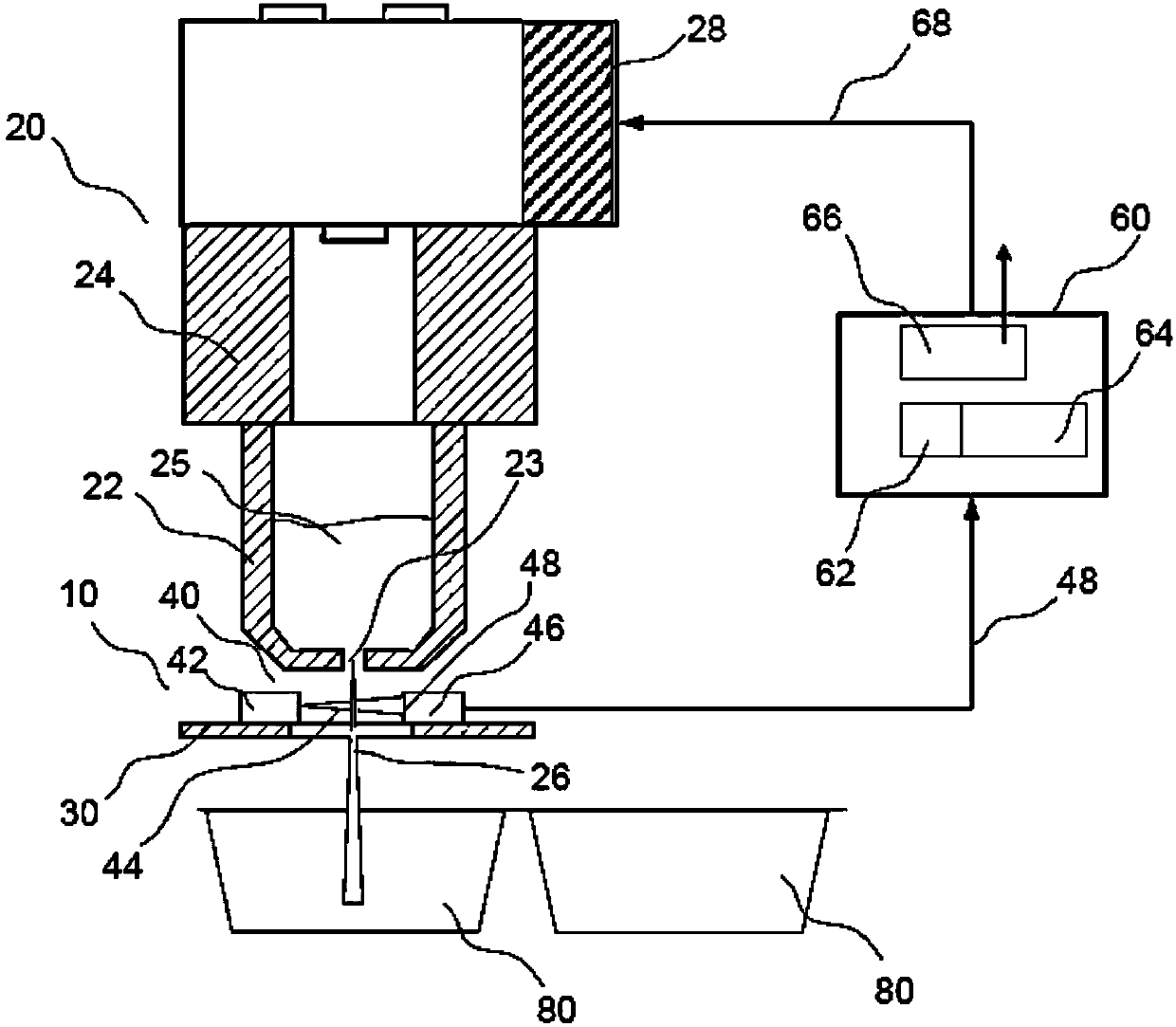
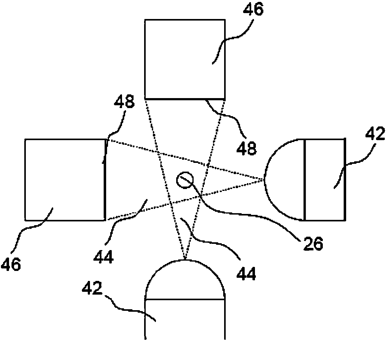
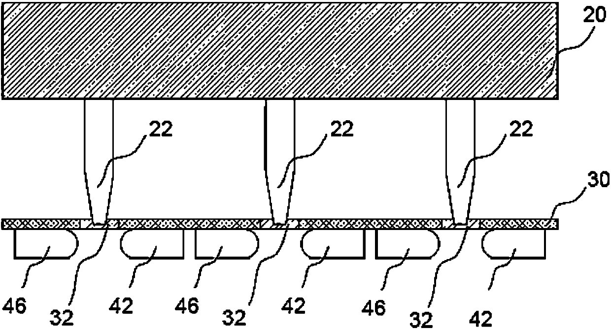
[0056] figure 1 A schematic diagram showing the general structure of the microdispensing device with optical control device of the present invention. For clarity, one of a plurality of dosing channels (English: dosing channel, also called: dosing channel, metering channel, etc.) is shown here. Each metering channel 22 of the micro-dispensing device 20 includes a drive or metering head 24 . The metering head is adapted to apply repeated pressure pulses to the liquid 25 in the metering channel 22 to force the liquid out of the nozzle 23 . The optical device 10 according to the invention is placed directly below the outlet of the metering channel 22 or the nozzle 23 . This essentially consists of a supported light barrier unit 40 with a light source 42 for generating a shaped light beam 44 which is projected onto a sensor surface 48 of a sensor 46 . The light source 42 ...


PUM


Abstract

Means and methods for dispensing small amounts of liquid from multi-channel microdispensing devices, suitable for use in automatic processing in biological assays and for the cultivation of cells andtissues, by means of optical control of the dosed liquid by specific light barrier units.

Description

technical field [0001] The invention relates to a method and means for controlling and automatically distributing a small amount of liquid by using a multi-channel microdispensing device, which is suitable for the automatic method of biological test and cell and tissue culture. Background technique [0002] The automatic metering (in English: metering) of small quantities of liquids using automated micro-dispensing robots is already known. With the aid of such devices, liquid media, so-called "biological liquids" such as cell suspensions, cell culture media, active substances and / or test substances are automatically metered into target containers or matrices. Typical applications are bioassays and automated cell and tissue culture ("single cell technology, single cell technology", "tissue engineering, tissue engineering"). Usually the target container is a multi-cell culture container for serial testing as well as for high-throughput processes, so-called microtiter plates o...

Claims


Application Information

Patent Timeline
IPC IPC(8): G01N35/04G01N35/10G01N21/39C12M1/00B01L3/00C12M3/00C12M1/36
CPCB01L3/00C12M23/40C12M41/06C12M41/48G01N21/39G01N35/04G01N35/10B01L3/0241B41J2/16579B41J2/2142G01N35/1009G01N35/1074B01L2200/061B01L2200/143B01L2300/0654B01L2400/0439G01N2035/1018G01N2035/1034G01N2035/1044B01L3/02B01L3/5027B01L2300/0861C12M29/00G01N35/1016G01N35/1065
Inventor 迈克尔·克林格克里斯托弗·拉斯克
Owner FRAUNHOFER GESELLSCHAFT ZUR FOERDERUNG DER ANGEWANDTEN FORSCHUNG EV
Why Eureka
Try Eureka