
Method for phased array calibration and calibration apparatus

A phased array and array calibration technology, applied in the field of phased array calibration, can solve the problems of large test space, test site limitations, and consume a lot of time, achieve accurate coupling coefficient, improve feasibility, and improve practicability. Effect

Active Publication Date: 2018-03-06
HUAWEI TECH CO LTD
View PDF3 Cites 33 Cited by
  • Summary
  • Abstract
  • Description
  • Claims
  • Application Information

AI Technical Summary

Problems solved by technology

[0004] However, the far-field test method usually requires a large test space, which limits the test site and is not conducive to the convenience of the test
At the same time, if faced with a large number of antenna devices, it takes a lot of time to test each unit in these antenna devices, resulting in low test efficiency

Method used


Image

  • Method for phased array calibration and calibration apparatus
  • Method for phased array calibration and calibration apparatus
  • Method for phased array calibration and calibration apparatus

Examples


Embodiment Construction

[0108] The embodiment of the present application provides a phased array calibration method and a calibration device, which can improve the detection efficiency, reduce the occupied area, and reduce the cost, thereby greatly reducing the time required for phased array calibration and improving the phase accuracy. Detection efficiency of array products.

[0109] The terms "first", "second", "third", "fourth", etc. (if any) in the specification and claims of the present application and the above drawings are used to distinguish similar objects, and not necessarily Used to describe a specific sequence or sequence. It is to be understood that the data so used are interchangeable under appropriate circumstances such that the embodiments of the application described herein, for example, can be practiced in sequences other than those illustrated or described herein. Furthermore, the terms "comprising" and "having", as well as any variations thereof, are intended to cover a non-exclu...


PUM


Abstract

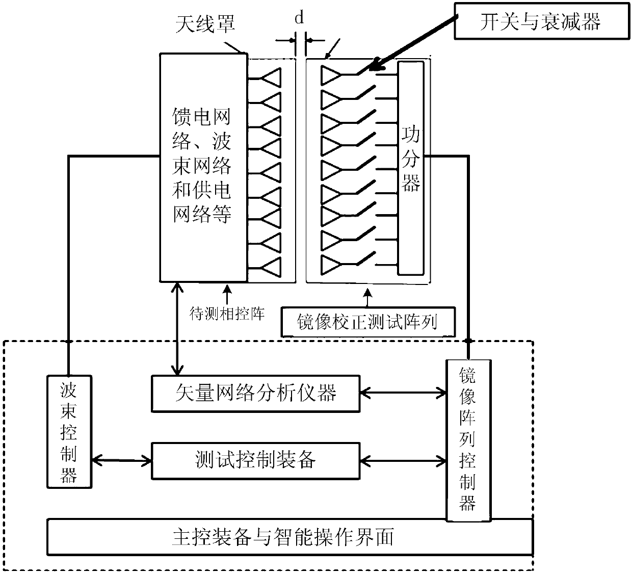
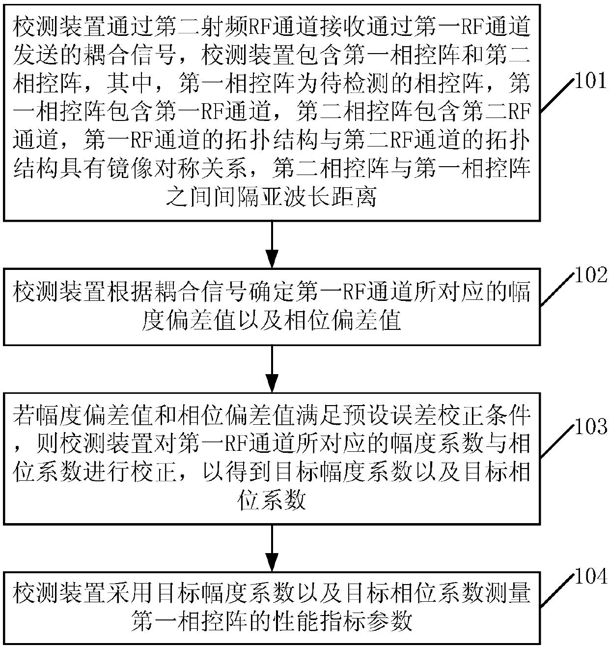
The application discloses a method for phased array calibration. The method is applied to a calibration device consisting of a first phased array and a second phased array. The first phased array includes a first RF channel and the second phased array includes a second RF channel. The topological structure of the first RF channel and the topological structure of the second RF channel forms a mirror symmetry relationship. The second phased array and the first phased array are spaced at a sub-wavelength distance. A coupling signal transmitted through the first RF channel is received by the second RF channel; according to the coupling signal, an amplitude deviation value and a phase deviation value corresponding to the first RF channel are determined; if a preset error correction condition issatisfied, an amplitude coefficient and phase coefficient corresponding to the first RF channel are corrected; and with a target amplitude coefficient and a target phase coefficient, a performance index parameter of the first phased array is measured. In addition, the invention also discloses a calibration apparatus. rapid amplitude and phase correction on all RF channels of a to-be-calibrated phased array is realized; the detection efficiency is improved; the occupied area is reduced; and the cost is lowered.

Description

technical field [0001] The present application relates to the communication field, and in particular to a phased array calibration method and calibration device. Background technique [0002] The basic principle of the phased array is to use the superposition and phase change of the radiation waveforms of the unit antennas to realize power combining and beam scanning. Its radiation performance is mainly determined by the unit antenna and beam control system, and is characterized by the far-field pattern. Due to the small spacing and strong mutual coupling between the antenna elements of the phased array antenna, the antenna gain decreases and the sidelobe level increases. In severe cases, not only cannot the beam be scanned accurately, but also the beam may be severely distorted. There are many factors that affect the performance of phased arrays, including device inconsistency in channel errors, manufacturing tolerances, assembly errors, environmental changes, mutual coupli...

Claims


Application Information

Patent Timeline
IPC IPC(8): G01R29/10G01R29/08
CPCG01R29/0871G01R29/10H01Q3/267H01Q3/2611H01Q3/2682G01R29/08H04B17/12H04W24/00H04W24/06
Inventor 葛广顶赵旭波赵德双
Owner HUAWEI TECH CO LTD
Learn More