
Preparation method of electronic equipment liquid cooling pipe assembly

A technology of electronic equipment and liquid-cooled tubes, which is applied in the field of preparation of buckle-type pipeline components, can solve problems such as low production efficiency, difficulty in ensuring dimensional accuracy, and welding defects, and achieve low assembly man-hours, good assembly adaptability, and high-quality products. good consistency

Active Publication Date: 2018-03-09
10TH RES INST OF CETC
View PDF6 Cites 4 Cited by
  • Summary
  • Abstract
  • Description
  • Claims
  • Application Information

AI Technical Summary

Problems solved by technology

However, the cold pipe components currently used mainly include copper pipes, corrugated pipes, rubber pipes, and polytetrafluoroethylene pipes. Among them, the dimensional accuracy of the external interface of the copper pipes is not easy to guarantee, the bellows is prone to fatigue and cracking, and the rubber pipes have poor adaptability to low-temperature environments.
The assembly methods of the cold pipe assembly generally include crimping type, welding type, and detachable type. Among them, the detachable type has high labor intensity, low production efficiency, and it is difficult to control the compression rate of the hose; the welding type can only be used for Some metal pipes can be welded, and it is not easy to ensure the size of the interface, and there may be welding defects; the crimping type requires special equipment, and the scientific calculation of the crimping amount is difficult, and the selection is basically based on experience, which is likely to cause crimping not in place and reduce the reliability of the product It may even cause liquid leakage, or excessive withholding may cause damage to the pipe joint 1 and cause quality problems

Method used


Image

  • Preparation method of electronic equipment liquid cooling pipe assembly
  • Preparation method of electronic equipment liquid cooling pipe assembly
  • Preparation method of electronic equipment liquid cooling pipe assembly

Examples


Embodiment Construction

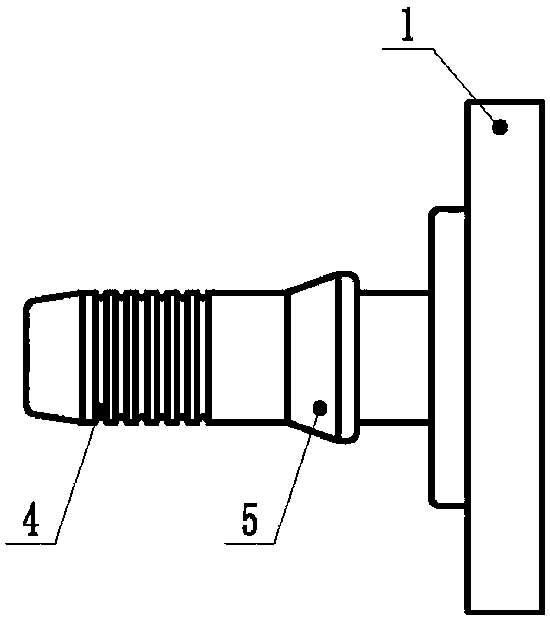
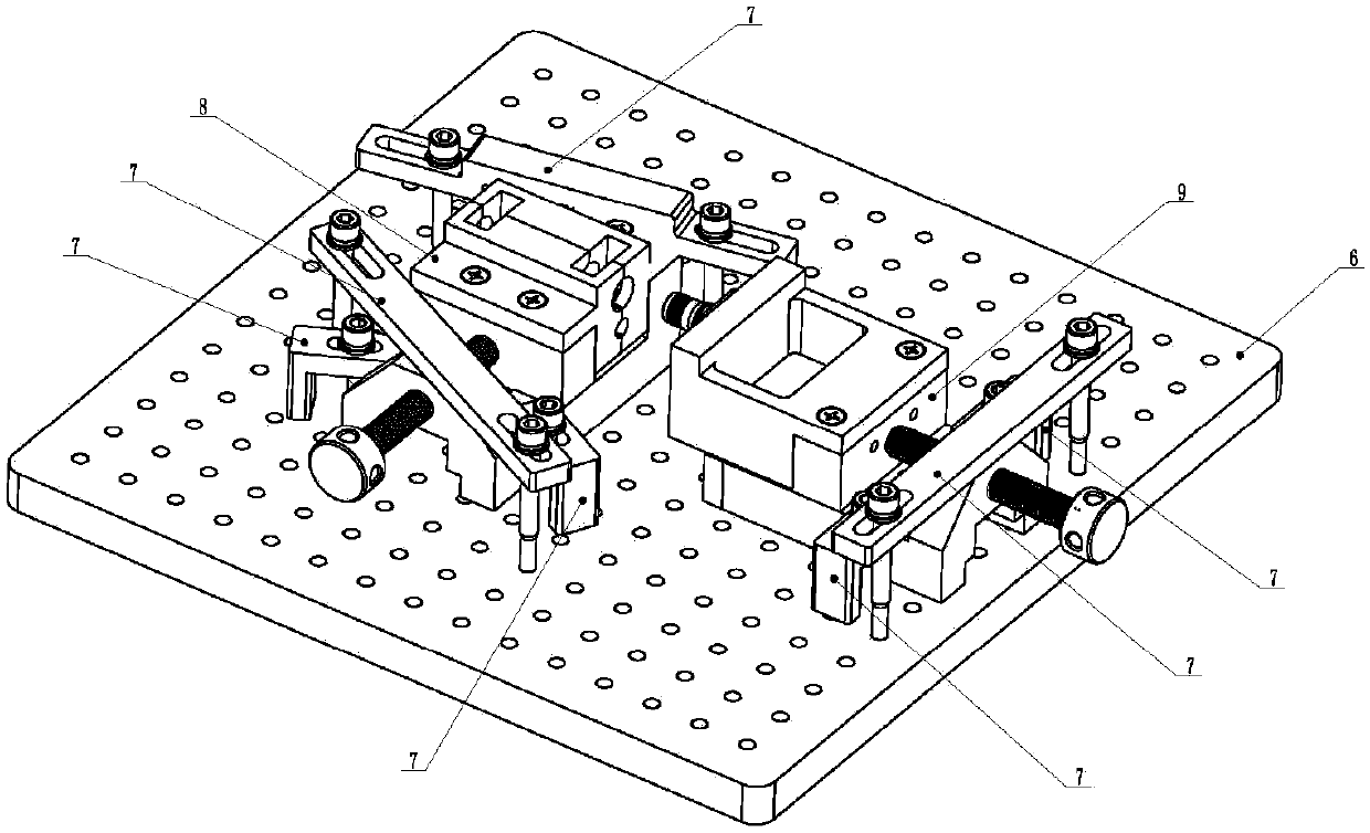
[0021] refer to figure 1 . According to the present invention, the stainless steel braided non-metallic hose 2 is used as the heat exchange flow channel, and the two ends of the non-metallic hose 2 are respectively inserted into the austenitic stainless steel-based sleeve 3, and the anti-rust aluminum-based pipe joints 1 fixedly connected at both ends are connected. On the end face of the tower-type step shaft, the three are integrated by mechanical crimping. During the preparation process, the wall thickness compression rate of the non-metallic hose 2 in the straight section of the arc-shaped groove of the pipe joint 1 is set to 40%-50%. 2 and sleeve 3 in the butt joint size of the assembly part, calculate the withholding amount of the non-metallic hose and pipe joint 1 in the straight section of the arc-shaped groove of the pipe joint 1, set the withholding parameters corresponding to the withholding equipment according to the withholding amount, and use the withholding To...


PUM


Abstract

The invention discloses a preparation method of an electronic equipment liquid cooling pipe assembly. According to the preparation method of the liquid cooling pipe assembly, the remarkable corrosionresistance is achieved, the pressure resistance is high, and the long-term work reliability is high. According to the technical scheme, a nonmetal hose (2) with stainless steel braiding serves as a heat exchange runner, the two ends of the nonmetal hose (2) are inserted into sleeves (3) to be in butt joint with the end faces of tower-type step shafts of pipe connectors (1) fixedly connected to thetwo ends, and the nonmetal hose (2) and the tower-type step shafts form a whole in a mechanical buckling manner. In the preparation process, corresponding buckling parameters of buckling equipment are set according to the buckling amount, a buckling tool die and the buckling equipment are used, after manufacturing of a basic cooling pipe assembly is completed, the basic cooling pipe assembly is expanded into a cooling pipe assembly in a two-way, three-way, four-way even three-dimensional five-way pipe assembly structure manner through cooperation of a cooling pipe assembly adapter (12) with astandard interface (13).

Description

technical field [0001] The invention relates to a heat transfer pipeline assembly, and mainly relates to a preparation method of a buckle-type pipeline assembly that takes away heat through cooling liquid. Background technique [0002] With the rapid development of electronic technology, the total power density of electronic components has increased significantly while the physical size has become smaller and smaller, and the high temperature environment will affect the performance of electronic components. Effectively solving the heat dissipation problem of electronic components has become a key technology in the manufacture of electronic components and electronic equipment. In recent years, with the improvement of miniaturization, modularization and high integration design requirements of electronic equipment, the heat flux density often reaches 7 to 10 times that of traditional air-cooled equipment. module, so the problem of heat dissipation is very prominent. Liquid co...

Claims


Application Information

Patent Timeline
IPC IPC(8): B25B27/10F28F21/00
CPCB25B27/10F28F21/00
Inventor 王胜胡国高吴伟赖复尧严宏
Owner 10TH RES INST OF CETC
Learn More