Medical imaging system and positioning method thereof

A medical imaging system and positioning method technology, applied in positioning, medical science, radio wave measurement system, etc., can solve the problems of time consumption, increased scanning work walking distance, inconvenient operation, and peripheral nerve stimulation of patients, so as to reduce The effect of positioning time, reducing walking, and improving work efficiency

Active Publication Date: 2018-03-09
SHANGHAI UNITED IMAGING HEALTHCARE
View PDF9 Cites 2 Cited by
  • Summary
  • Abstract
  • Description
  • Claims
  • Application Information

AI Technical Summary

Problems solved by technology

[0004] In the first step of the existing scanning position positioning method, the horizontal movement will consume a certain amount of time even if it is accelerated, and the acceleration process may also cause peripheral nerve stimulation in the patient.
In addition, the keys to control the movement of the hospital bed are all on the control panel of the magnet, and doctors need to be close to the magnet for operation, which increases the walking distance and inconvenient operation during the scanning work

Method used


Image

  • Medical imaging system and positioning method thereof
  • Medical imaging system and positioning method thereof
  • Medical imaging system and positioning method thereof

Examples


Embodiment 1

[0041] In this embodiment, the medical imaging system selects the magnetic resonance system, the signal generator is an ultrasonic (signal) transmitter, and the signal receiver selects an ultrasonic probe.

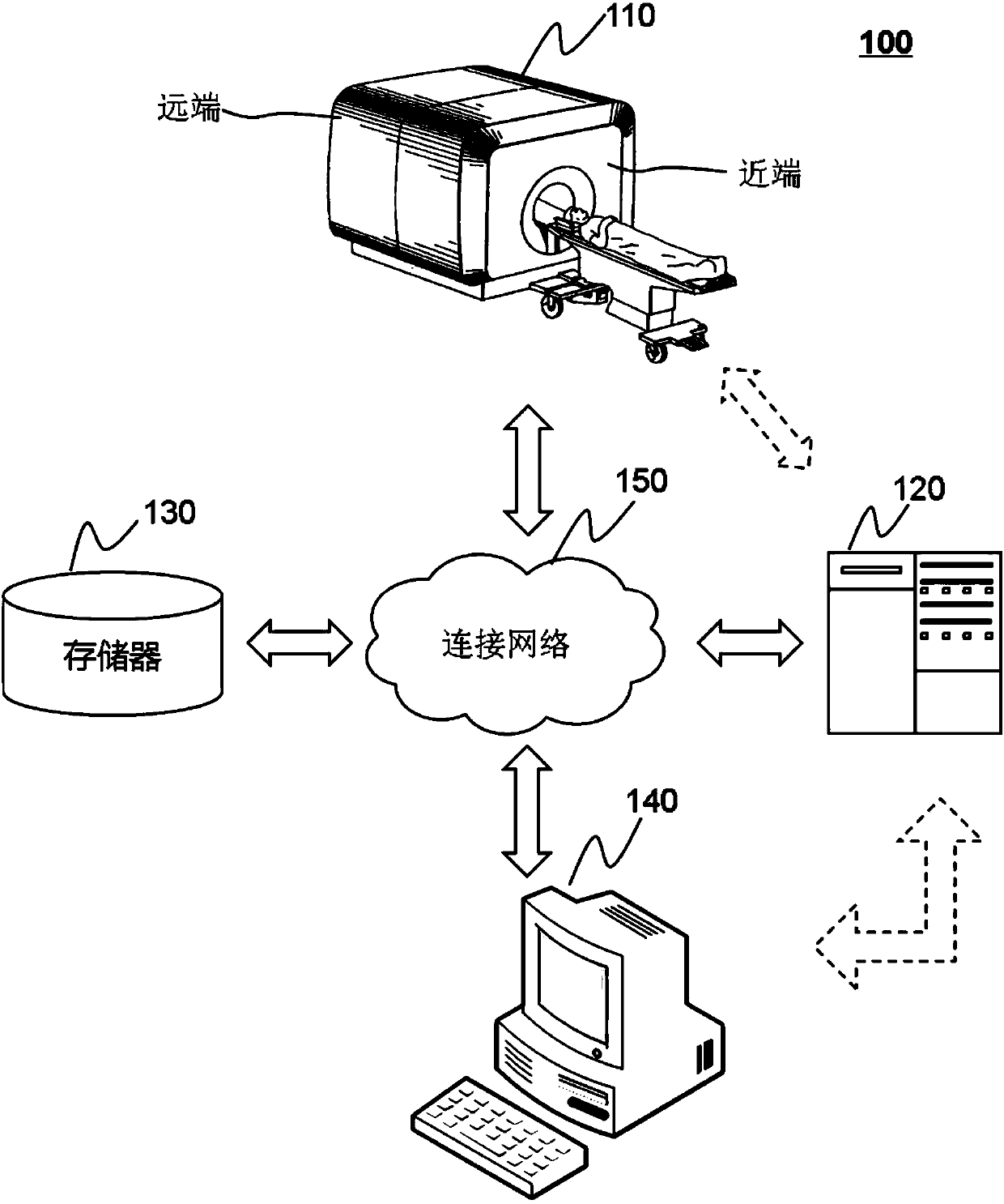
[0042] Figure 1a It is a structural block diagram of the magnetic resonance system in Embodiment 1 of the present invention. This embodiment is applicable to the situation of positioning between the target area to be scanned of the subject and the hospital bed in magnetic resonance imaging. Such as Figure 1aAs shown, the magnetic resonance system 100 specifically includes: a scanner 110 , a controller 120 , a memory 130 , a display 140 and a connection network 150 . The scanner 110 may include a magnet module and a radio frequency (RF) module. The magnet module may include magnets and / or gradient magnetic field generators. The magnet can generate a static magnetic field B0 during an MRI procedure. The magnets can be of various types including, for example, permanent ma...

Embodiment 2

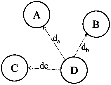
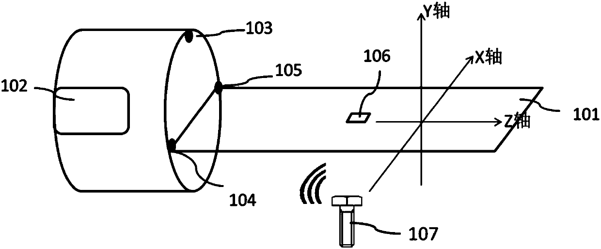
[0059] figure 2 It is a flow chart of the positioning method of the medical imaging system provided by the second embodiment of the present invention. The medical imaging system includes: a scanner, forming a scanning cavity, the scanning cavity has a main longitudinal axis of a proximal end and a distal end, the proximal end of the main longitudinal axis is the end face of the scanning cavity close to the doctor, and the far end of the main longitudinal axis is the opposite side of the proximal end The end face, the center of the main longitudinal axis corresponds to the center of the scanning cavity, and the FOV area is formed at this position; the hospital bed, which can move in the scanning cavity; the signal generator, which can be placed above the patient bed; multiple signal receivers, distributed in the On the above-mentioned scanner, specifically, it can be arranged on the end face corresponding to the near end of the scanner. The positioning method of the above-men...

Embodiment 3

[0066] image 3 It is a flow chart of the positioning method of the medical imaging system provided by Embodiment 3 of the present invention. This method can be realized by the magnetic resonance system in the above embodiment, such as image 3 As shown, the positioning method of the magnetic resonance system specifically includes the following steps:

[0067] S310. Place the ultrasonic signal generator in a first vertical plane corresponding to the subject's target area, and use the ultrasonic signal generator to transmit an ultrasonic signal or a detection signal.

[0068] Specifically, during the examination process of the magnetic resonance imaging, the subject should lie on a movable hospital bed and be fixed in a supine position or a prone position. The doctor holds the remote controller and stands beside the hospital bed, and places the remote controller, that is, the ultrasound signal generator, in the first vertical plane corresponding to the subject's target area to...


PUM


Abstract

The embodiment of the invention discloses a medical imaging system and a positioning method thereof. The medical imaging system comprises a scanning instrument, a hospital bed, a signal transmitter, signal receivers and a controller, wherein the scanning instrument comprises a scanning chamber which is provided with main longitudinal shafts at the near end and the far end; the signal transmitter is used for transmitting a probing signal; the signal receivers are distributed on the scanner and are used for receiving the probing signal as well as acquiring the probing information based on the probing signal; and the controller is used for determining the relative location relation between the hospital bed and the centers of the main longitudinal shafts of the scanning chamber based on the probing signal as well as controlling the hospital bed to the centers of the main longitudinal shafts of the scanner based on the relative location relation. With the adoption of the medical imaging system in the embodiment, the positioning time of a part to be scanned can be reduced, the peripheral nerve of a patient can be prevented from being excited during moving at a plurality of times, and thecheckup experience of the patient is improved.

Description

technical field [0001] Embodiments of the present invention relate to the technical field of medical imaging, and in particular to a medical imaging system and a positioning method thereof. Background technique [0002] Medical imaging refers to the technology and processing process of obtaining internal tissue images of the human body or a certain part of the human body in a non-invasive manner for medical treatment or medical research. Among them, magnetic resonance imaging (Magnetic Resonance Imaging, MRI) technology is one of the main imaging technologies applied to medical examination. [0003] Usually, before the scanning of the magnetic resonance sequence starts, it is necessary to position the part of the patient to be scanned to the exact center of the magnet of the magnetic resonance imaging device. Existing medical imaging equipment at least includes movable hospital beds, scanning equipment and control equipment. The patient lies on the hospital bed and moves r...

Claims


Application Information

Patent Timeline
IPC IPC(8): G01R33/30G01S5/22A61B6/03A61B5/055
CPCA61B5/055A61B6/032A61B6/037G01R33/307G01S5/22
Inventor 胡均普
Owner SHANGHAI UNITED IMAGING HEALTHCARE
Why Eureka
Try Eureka