Clamp for milling joint face of gearbox shell and use method of clamp

A joint surface and gearbox technology, applied in the direction of clamping, manufacturing tools, supports, etc., can solve the problems of difficult clamping, easy deformation of the workpiece, poor machining accuracy of the joint surface, etc., to avoid vibration, reduce clamping time, improve The effect of machining accuracy

Pending Publication Date: 2018-03-13
CHUZHOU YUEDA IND
View PDF5 Cites 10 Cited by
  • Summary
  • Abstract
  • Description
  • Claims
  • Application Information

AI Technical Summary

Problems solved by technology

[0004] The technical problem to be solved by the present invention is that the clamp for the milling joint surface of the transmission case is not easy to clamp, the machining accuracy of the joint surface is poor, and the workpiece is easy to deform. A clamp for the milling joint surface of the transmission case and its use method are provided to solve the above problems

Method used


Image

  • Clamp for milling joint face of gearbox shell and use method of clamp
  • Clamp for milling joint face of gearbox shell and use method of clamp
  • Clamp for milling joint face of gearbox shell and use method of clamp

Examples


Embodiment Construction

[0026] In order to have a further understanding and recognition of the structural features and the achieved effects of the present invention, the preferred embodiments and accompanying drawings are used for detailed description, as follows:

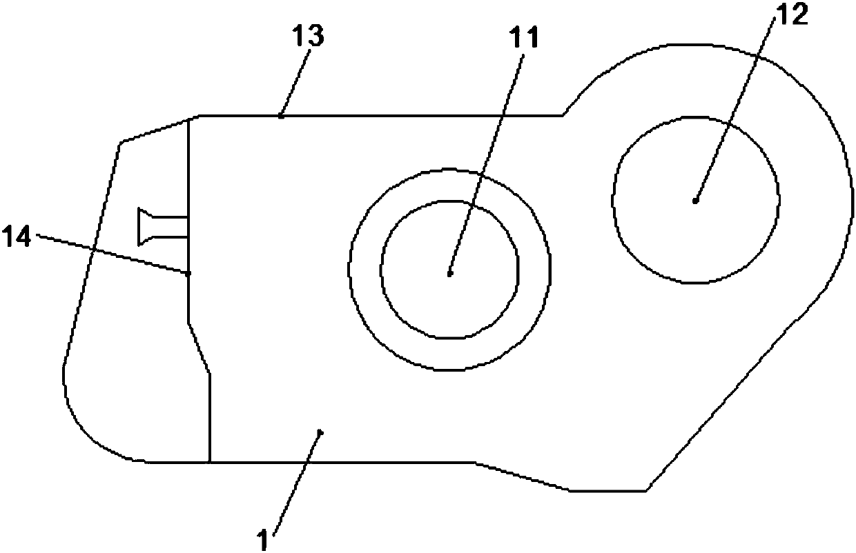
[0027] Such as figure 1 As shown, the gearbox housing 1 is a thin-walled part, and the middle and upper right parts are respectively provided with an assembly hole 11 and an assembly hole 2 12, and the blank surface near the side edge 13 of the housing 1 is smooth and flat. A turning surface 14 is provided at the left middle part of the housing 1 , and the left edge of the housing 1 is the thinnest part of the housing 1 .

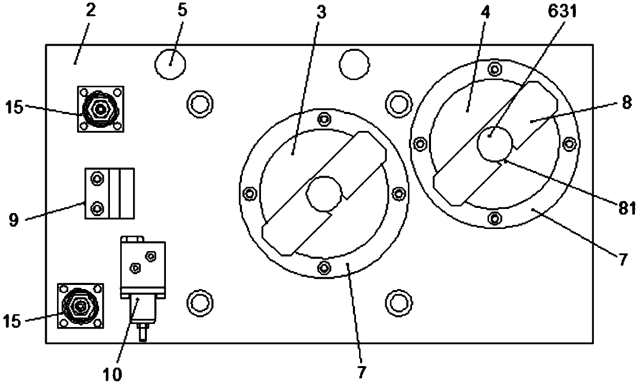
[0028] Such as figure 2 , image 3 As shown, the jig for milling the joint surface of the transmission case includes a base plate 2, and the base plate 2 is provided with a counterbore corresponding to the position of the assembly hole on the housing 1, wherein the counterbore 3 is connected to the assembly hole 11 ...


PUM


Abstract

The invention provides a clamp for a milling joint face of a gearbox shell and a use method of the clamp. The clamp comprises a bottom plate. Countersinks corresponding to assembling holes in the shell in position are formed in the bottom plate. A pressing device is arranged on each countersink. Fixed pressing force can be set on each pressing device. A stop dog device clamped to the turning faceof the shell and a support device with the height adjusting and height self-locking functions are arranged on the bottom plate. The use method of the clamp comprises the steps that (1), a workpiece isclamped; (2), the workpiece is tensioned by oil cylinders; and (3), the workpiece is abutted by the support device and locked. The clamp and the use method have the beneficial effects that the degreeof automation is high, the clamping pressure is fixed, the problems of tool vibration, extremely-poor flatness and the like existing in the clamping and machining processes of the thin wall shell aresolved, and the machining accuracy of the milling joint face of the gear shell is guaranteed.

Description

technical field [0001] The invention relates to the technical field of clamping devices, in particular to a clamp for milling joint surfaces of gearbox casings and a method for using the same. Background technique [0002] The gearbox housing belongs to the cavity type thin-walled parts. The housing is provided with assembly holes for assembling bearings and brake discs and other components. For oil filling and oil draining, the housing is provided with oil filling holes and oil drain holes. In order to keep the inside of the gearbox at atmospheric pressure, the housing is also provided with There are several ventilation holes. [0003] In the machining process of the gearbox housing, the machining of the milling joint surface is a very important process in the machining process of the gearbox housing, and its machining accuracy will directly affect the product quality of the gearbox housing. Since this type of shell is a thin-walled part, there are problems of tool vibrat...

Claims


Application Information

Patent Timeline
Patent Type & Authority Applications(China)
IPC IPC(8): B23Q3/08
CPCB23Q3/082
Inventor 黄泽伟
Owner CHUZHOU YUEDA IND
Why Eureka
Try Eureka