Method of rapidly determining fiber Bragg grating (FBG) reflectance spectrum abnormal mode

A reflection spectrum and pattern technology, which is applied in character and pattern recognition, using optical devices to transmit sensing components, converting sensor output, etc., can solve the problems of inability to include abnormal patterns, inability to judge FBG reflection spectrum abnormal patterns, and high signal-to-noise ratio , achieve positive practical significance and guiding role, improve fault diagnosis efficiency, and achieve high recognition accuracy

Active Publication Date: 2018-03-13
BEIJING INST OF SPACECRAFT ENVIRONMENT ENG
View PDF4 Cites 4 Cited by
  • Summary
  • Abstract
  • Description
  • Claims
  • Application Information

AI Technical Summary

Problems solved by technology

At present, the commonly used FBG reflection spectrum working mode recognition algorithm is based on the fact that the FBG sensor works in a normal atmospheric temperature (-40°C to 50°C). The signal-to-noise ratio of the FBG reflection spectrum is high. The peakless mode caused by the small signal-to-noise ratio reduction cannot include the abnormal mode in the vacuum thermal environment, and the commonly used FBG reflection spectrum working mode recognition algorithm cannot judge the abnormal mode of the FBG reflection spectrum in the extreme space environment
Moreover, the currently commonly used FBG reflection spectrum working mode recognition algorithm uses the full bandwidth of FBG reflection spectrum (such as 1510nm to 1590nm) to participate in the operation, with a large amount of data and complex algorithms. The recognition algorithm based on neural networks also requires sample data for pre-training, resulting in recognition less efficient

Method used


Image

  • Method of rapidly determining fiber Bragg grating (FBG) reflectance spectrum abnormal mode
  • Method of rapidly determining fiber Bragg grating (FBG) reflectance spectrum abnormal mode
  • Method of rapidly determining fiber Bragg grating (FBG) reflectance spectrum abnormal mode

Examples


Embodiment Construction

[0029] Hereinafter, a method for quickly determining the abnormal mode of the FBG reflection spectrum of the present invention will be described in detail with reference to the accompanying drawings, but the description is only exemplary and is not intended to limit the protection scope of the present invention in any way.

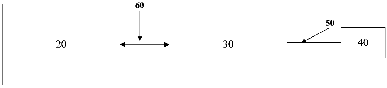
[0030] Such as figure 1 As shown, the hardware composition block diagram of the FBG reflection spectrum obtained by the fiber grating demodulator includes: a host PC 20, a fiber grating demodulator 30, an FBG sensor 40, a transmission fiber 50, an Ethernet cable or a USB transmission line 60. The fiber grating demodulator 30 and the FBG sensor 40 are connected through the transmission fiber 50. The fiber grating demodulator 30 obtains the reflection spectrum of the FBG 40, and converts it into a two-dimensional reflection spectrum data sequence through its photoelectric conversion and mode conversion, via an Ethernet cable or USB The transmission line 60 is s...


PUM

PropertyMeasurementUnit
Bandwidthaaaaaaaaaa

Abstract

The present invention discloses an FBG reflectance spectrum abnormal mode rapid discrimination method. The method comprises the following steps of 1) obtaining an FBG reflectance spectrum via a fibergrating demodulator, and converting the FBG reflectance spectrum into a digital sampling signal to send to an upper PC; 2) setting an alarm parameter on the PC; 3) rapidly discriminating the normal mode and the abnormal mode of the FBG reflectance spectrum within the FBG wavelength range [lambda min, lambda max] and according to the set alarm parameter. The method solves the problems that under the atmospheric ambient temperature environment and the high vacuum thermal environment, the FBG reflectance spectrum abnormal mode is identified incompletely, and a fault mode is low in identificationaccuracy, has the characteristics of being simple and rapid in algorithm, little in mode discrimination participation data quantity and high in abnormal mode identification accuracy, and being not influenced by the low spectrum signal to noise ratio, and enables the fault diagnosis efficiency of an FBG under the regular usage environment and the extreme environment to be improved substantially.

Description

Technical field [0001] The invention belongs to the technical field of optical fiber sensing, and specifically relates to a method for quickly determining the abnormal mode of the FBG reflection spectrum. Background technique [0002] Fiber Bragg Grating (FBG) sensor is currently a research hotspot in the field of optical fiber sensors, and it is also the most extensive and market potential optical fiber sensor in sensor research and application. It can meet the needs of the entire star and its large exposed structural parts (such as network Antenna, truss structure, solar wing, robotic arm, etc.) High vacuum (pressure is about 10 -4 Pa level) heat (-150℃~150℃ cycle) test application requirements. [0003] FBG mainly judges the change of the physical quantity (temperature or strain, etc.) to be measured by observing the peak drift of the reflection spectrum, so it can accurately, comprehensively and quickly identify the working mode of the FBG reflection spectrum, and improve the F...

Claims


Application Information

Patent Timeline
IPC IPC(8): G01D5/353G01D5/38G06K9/62
CPCG01D5/35354G01D5/38G06F18/285
Inventor 张景川王晶杨晓宁裴一飞廖韬李超李天水刘哲
Owner BEIJING INST OF SPACECRAFT ENVIRONMENT ENG
Why Eureka
Try Eureka