Spatial camera with surrounding support type electronics assembly

A technology of space camera and electronics, which is applied in the field of space optics, can solve problems affecting camera assembly and adjustment, and achieve the effects of improving mechanical properties, high rigidity of the overall structure, and reducing stress concentration

Pending Publication Date: 2018-03-13
XI'AN INST OF OPTICS & FINE MECHANICS - CHINESE ACAD OF SCI +1
View PDF0 Cites 0 Cited by
  • Summary
  • Abstract
  • Description
  • Claims
  • Application Information

AI Technical Summary

Problems solved by technology

[0005] The object of the present invention is to provide a space camera with a surrounding support type electronic assembly, which solves the te

Method used


Image

  • Spatial camera with surrounding support type electronics assembly
  • Spatial camera with surrounding support type electronics assembly
  • Spatial camera with surrounding support type electronics assembly

Examples


Embodiment Construction

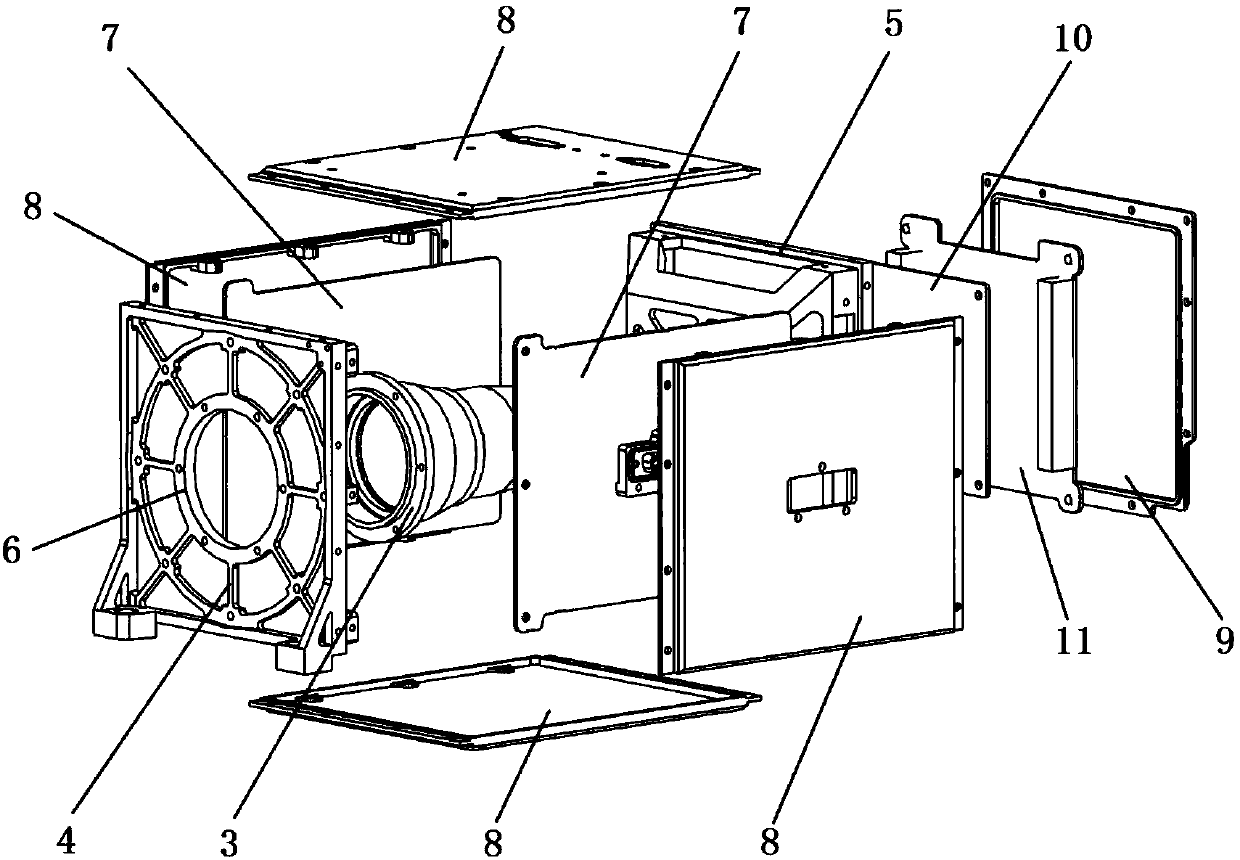
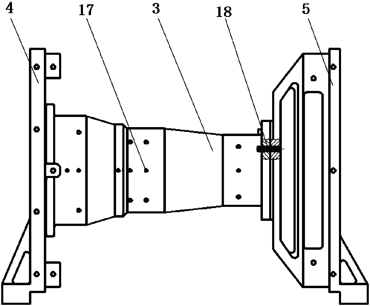
[0043] see figure 2 , the present invention provides a kind of space camera with surrounding support type electronic assembly, the structure of its preferred embodiment comprises optical lens barrel 3, and the front of optical lens barrel 3 is provided with front support 4, and the back side of optical lens barrel 3 is provided with The rear bracket 5 , the front bracket 4 and the rear bracket 5 are all perpendicular to the optical axis of the optical lens barrel 3 ; the front bracket 4 is provided with a circular light hole 6 corresponding to the position of the optical lens barrel 3 . like image 3 As shown, the optical lens barrel 3 is matched with the front bracket 4 and the rear bracket 5 through seams, and is connected into one body by screws. The front bracket 4 and the optical lens barrel 3, the rear bracket 5 and the optical lens barrel 3 are all positioned by cylindrical pins 18; the optical lens barrel 3 is provided with threaded glue injection holes 17.

[0044]...


PUM


Abstract

The invention belongs to the technical field of space optics, and particularly relates to a spatial camera with a surrounding support type electronics assembly. The camera comprises an optical lens barrel, wherein a front support is arranged on the front side of the optical lens barrel, a rear support is arranged on the back side of the optical lens barrel. The front support and the rear support are both perpendicular to the optical axis of the optical lens barrel; and a round light through hole corresponding to the position of the optical lens barrel is formed in the front support. The two sides of the optical lens barrel are respectively provided with a circuit board, and the circuit boards are parallel to the optical axis of the optical lens barrel and are fixedly connected with the front support and the rear support respectively. Four side cover plates are arranged on the periphery of the optical lens barrel, one face of the rear support is fixedly connected with the optical lens barrel, and a rear cover plate is installed on the other face of the rear support, and a focal panel and a bus plate are arranged between the rear support and the rear cover plate. A traditional electronic assembly as a separate module is abandoned, so that a main support is located at the part of an optical assembly, and the electronic assembly surrounds the main support. The overall structural rigidity is high, and the mechanical property is improved.

Description

technical field [0001] The invention belongs to the technical field of space optics, and in particular relates to a space camera with surrounding supporting electronic components. Background technique [0002] A space camera is an optical instrument installed on a space platform, which is mainly used to capture images of earth or space targets in the ultraviolet, visible or infrared optical bands. A complete space camera system covers a variety of comprehensive technologies such as optical imaging, mechanical support, and electrical control. [0003] Existing space cameras usually adopt a modular structure design, and each module is designed and produced separately, and the modules are fixedly connected by mechanical means, and finally the assembly and adjustment test of the whole machine is carried out. like figure 1 As shown, in the existing space camera structure, the optical assembly 1 and the electronic assembly 2 are arranged in a straight line, and the structure is ...

Claims


Application Information

Patent Timeline
IPC IPC(8): G03B17/12G02B7/00
CPCG02B7/00G03B17/12
Inventor 叶径吴萌源胡永明段永强刘杰王炜李霞
Owner XI'AN INST OF OPTICS & FINE MECHANICS - CHINESE ACAD OF SCI
Why Eureka
Try Eureka