Method for controlling second order sliding mode of bearingless synchronous reluctance motor

A synchronous reluctance motor, second-order sliding mode technology, applied in motor generator control, AC motor control, electronic commutation motor control and other directions, can solve problems such as poor control performance, and achieve fast response speed, high performance speed, Radial displacement control stabilizes the effect

Inactive Publication Date: 2018-03-13
JIANGSU UNIV
View PDF4 Cites 3 Cited by
  • Summary
  • Abstract
  • Description
  • Claims
  • Application Information

AI Technical Summary

Problems solved by technology

[0006] The purpose of the present invention is to propose a second-order sliding mode control method for a bearingless synchronous reluctance motor, to solve the problem of poor control performance of the bearingless synchronous reluctance motor control system under large disturbances, and to improve the performance of the bearingless synchronous reluctance motor system. Excellent response speed, reduce overshoot, enhance robustness, so that the entire control system has good control performance

Method used


Image

  • Method for controlling second order sliding mode of bearingless synchronous reluctance motor
  • Method for controlling second order sliding mode of bearingless synchronous reluctance motor
  • Method for controlling second order sliding mode of bearingless synchronous reluctance motor

Examples


Embodiment Construction

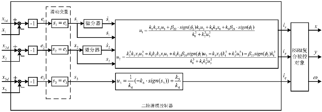
[0027] The concrete implementation of the present invention divides following several steps:

[0028] 1. Establish the mathematical model of the bearingless synchronous reluctance motor. Let the state variable be The system input is u=[u 1 u 2 u 3 ] T =[i q i x i y ] T , the system output is y=[y 1 the y 2 the y 3 ] T =[x y ω] T , then the mathematical model of the bearingless synchronous reluctance motor can be expressed in the form of state equation as follows:

[0029]

[0030] In the formula, m is the mass of the rotor, K m1 、K m2 、k s are constants, i d is the d-axis component of the stator current, P M is the number of pole pairs of the torque winding, J is the moment of inertia of the rotor, L d is the motor d-axis inductance, L q is the motor q-axis inductance, T L is the load torque, F zx is the radial force applied along the x-axis direction, F zy is the applied radial force along the y-axis direction.

[0031] 2. According to the sys...


PUM


Abstract

The invention discloses a method for controlling the second order sliding mode of a bearingless synchronous reluctance motor. According to a mathematic model of the bearingless synchronous reluctancemotor, a traditional sliding mode control method is applied to rotational speed control, the rotational speed of the bearingless synchronous reluctance motor reaches a preset rotational speed in finite time and the bearingless synchronous reluctance motor operates stably, the method for controlling the second order sliding mode is applied to radial displacement control of x axis and y axis, and the radial displacement of x axis and the radial displacement of y axis are stabilized to be zero in finite time respectively. The sliding mode controller is formed by rotational speed control based onfirst order sliding mode and displacement control based on second order sliding mode together, and a non-linear system of the bearingless synchronous reluctance motor is directly controlled, so that the dynamic characteristics and operation quality of the bearingless synchronous reluctance motor are effectively improved, the robustness of the system is enhanced, the chattering phenomena of the system is weakened, and the method is beneficial for engineering realization.

Description

technical field [0001] The invention relates to a second-order sliding mode control method for a bearingless synchronous reluctance motor, which is suitable for high-performance nonlinear control of a bearingless synchronous reluctance motor and belongs to the technical field of electric drive control. Background technique [0002] The bearingless synchronous reluctance motor combines the magnetic bearing technology with the traditional synchronous reluctance motor, and has the characteristics of high-performance drive such as high-speed, high-precision, no lubrication, no friction, and maintenance-free. At the same time, because the rotor has no permanent magnets and excitation windings, it has the advantages of simple structure, low cost, low loss, high efficiency, and low temperature rise. Broad application prospects. [0003] The bearingless synchronous reluctance motor is a multivariable, strongly coupled nonlinear system. When the motor is running in levitation, ther...

Claims


Application Information

Patent Timeline
Patent Type & Authority Applications(China)
IPC IPC(8): H02P21/00H02P21/05H02P25/098
CPCH02P21/0007H02P21/05H02P25/098
Inventor 刁小燕朱熀秋
Owner JIANGSU UNIV
Why Eureka
Try Eureka