
Vacuum inflating equipment and realizing method

An inflatable equipment and vacuum technology, applied in container filling methods, mechanical equipment, container discharge methods, etc., can solve the problems of safety risks, long inflation time, low vacuum degree, etc., to achieve constant temperature control and improve pumping efficiency. and vacuum degree, the effect of improving gas purity

Active Publication Date: 2018-03-16
BEIJING INST OF AEROSPACE CONTROL DEVICES
View PDF6 Cites 6 Cited by
  • Summary
  • Abstract
  • Description
  • Claims
  • Application Information

AI Technical Summary

Problems solved by technology

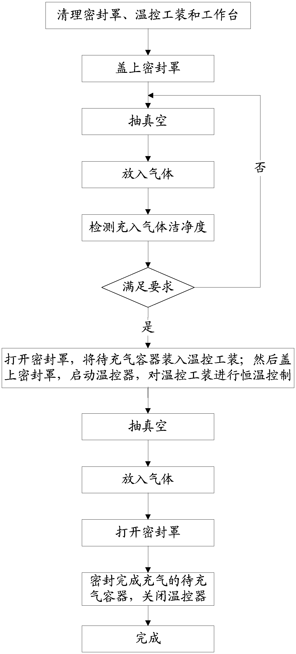
This method lacks quantitative control over the inflation process, which is mainly manifested in the following aspects: (1) The temperature of the inflation and sealing environment changes with the temperature of the working environment, so it is impossible to accurately control the temperature of the gas inflated, and there is air leakage caused by changes in the ambient temperature during the sealing process. The risk of inhaling the inflatable container; (2) the lack of cleanliness testing of the inflated gas makes it difficult to ensure the cleanliness of the inflated gas; (3) the lack of effective control of the gas pressure during the inflation process poses a safety risk; (4) only mechanical The pump is vacuumed, the vacuum degree is low, and it needs to be pumped and pumped repeatedly, and the inflation time is long, which affects the purity and production efficiency of the gas charged.

Method used


Image

  • Vacuum inflating equipment and realizing method
  • Vacuum inflating equipment and realizing method
  • Vacuum inflating equipment and realizing method

Examples


Embodiment Construction

[0025] The present invention will be described in further detail below in conjunction with the accompanying drawings and embodiments. It should be understood that the specific embodiments described here are only used to explain the present invention, but not to limit the present invention. In addition, it should be noted that, for the convenience of description, only some structures related to the present invention are shown in the drawings but not all structures.

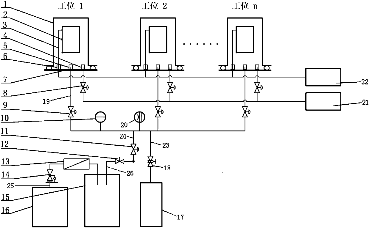
[0026] figure 1 It is a structural diagram of a vacuum inflation device in an embodiment of the present invention, and the vacuum inflation device is applicable to the situation where the sealed cavity of a precision instrument or instrument needs to be inflated. refer to figure 1 , a kind of vacuum inflating equipment provided in this embodiment includes a sealing cover 1, a temperature control tooling 2, a workbench 7, a temperature controller 22, a cleaning instrument 21, an inflating device and a molecular pu...


PUM


Abstract

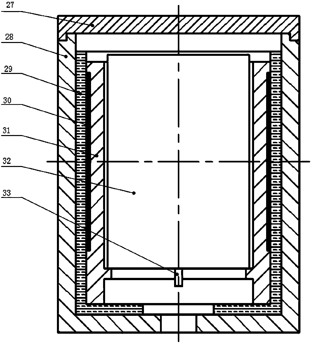
The invention discloses vacuum inflating equipment and a realizing method. The vacuum inflating equipment comprises a sealing cover, a temperature-control tooling, a worktable, a temperature controller, a clean instrument, an inflating device and a molecular pump; an air pumping port, an air pumping and deflating port and a sealing socket are mounted on the worktable; the temperature-control tooling is mounted in a closed space formed by the sealing cover and the worktable; the air pumping and deflating port outward introduces an air pumping and deflating total pipeline which communicates withthe molecular pump and the inflating device; the air pumping and deflating total pipeline is further provided with a thin film gauge and an ionization gauge; the air pumping port outward introduces acleanliness measuring pipeline which is further connected with the clean instrument; and the temperature controller is connected with a temperature control circuit of the temperature-control toolingthrough the sealing socket. According to the vacuum inflating equipment, guarantee of purity, cleanliness, temperature and pressure of gas inflated into a sealing cavity of a precision instrument is achieved, the production quality and the efficiency of products are improved, and the service lives of the products are prolonged.

Description

technical field [0001] The invention relates to airtight container inflation technology, in particular to a vacuum inflation device and a realization method. Background technique [0002] In the field of precision instruments and meters, some components or components need to be sealed in an air-filled container to work normally. The gas filled mainly has the following functions: (1) Provide a clean working environment and ensure the reliability of precision components. and durability, to prevent excess contamination from affecting the stability of components; (2) Filling the inflatable container with a specific gas facilitates the leak detection of the inflatable container after the sealing is completed. For example, after filling helium, the mass spectrometer (3) Fill high-purity clean inert gas to prevent oxidation or volatilization of materials in the internal components of the inflatable container, prevent qualitative change of materials or pollution of the operating env...

Claims


Application Information

Patent Timeline
IPC IPC(8): F17C5/06F17C13/02F17C13/04
CPCF17C5/06F17C13/02F17C13/025F17C13/026F17C13/04F17C2223/0123F17C2250/0605F17C2250/0626F17C2250/0631
Inventor 孙文利胡建忠黄炎张佐刘振龙李刚
Owner BEIJING INST OF AEROSPACE CONTROL DEVICES
Learn More