Eureka AIR delivers breakthrough ideas for toughest innovation challenges, trusted by R&D personnel around the world.

Gasification furnace built-in tar gasification circulating system

A technology of tar gasification and circulation system, which is applied in the mechanical details of gasification device, gasification process, moving parts of gasifier, etc., which can solve the problem of less chain safety guarantee of gas production mechanism, poor sustainable gas production capacity, and air pollution and other issues, to achieve the effect of high safety interlocking coefficient and automation degree, strong sustainable gas production capacity, and less smoke and tar emissions

Active Publication Date: 2016-04-13
ZHEJIANG JIUFAN NEW ENERGY TECH CO LTD
View PDF4 Cites 2 Cited by
  • Summary
  • Abstract
  • Description
  • Claims
  • Application Information

AI Technical Summary

Problems solved by technology

[0003] The existing biomass gasifier has high technical requirements in the operation process, troublesome use, low purity of the output gas, serious tar clogging of pipelines, low utilization value, poor sustainable gas production capacity, and smoke and tar emissions during use Cause secondary pollution, cause greater pollution to the air, low degree of automation, less chain security guarantee for the entire gas production mechanism, and have certain potential safety hazards

Method used


Image

  • Gasification furnace built-in tar gasification circulating system
  • Gasification furnace built-in tar gasification circulating system
  • Gasification furnace built-in tar gasification circulating system

Examples


Embodiment Construction

[0021] The present invention will be further described below through specific embodiments and accompanying drawings.

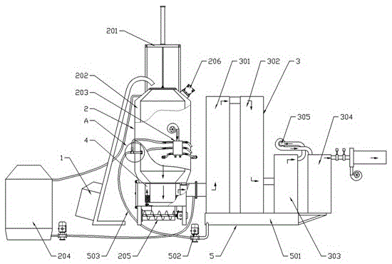
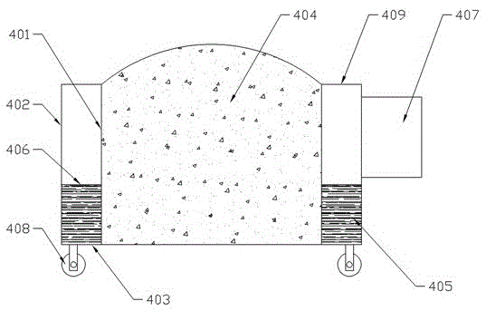
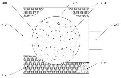
[0022] The implementation method is as follows: Figure 1-6 As shown, the gasification furnace built-in tar gasification circulation system includes a feeding device 1, a gasification device 2, and a separation cooling device 3 connected in sequence. The gasification device 2 includes a furnace body 202, and an automatic switch cover is provided on the top of the furnace body 202. Mechanism 201, a vibrator 206 is provided outside the furnace body 202, an air inlet mechanism 203 and a cooling mechanism 204 are connected outside the furnace body 202, an ash discharge mechanism 205 is provided at the bottom of the furnace body 202, and a tar gasification device is provided above the ash discharge mechanism 205 4. The tar gasification mechanism 4 includes an inner tank 401 and an outer tank 402. The top and bottom of the area between the inner tank 401 and the out...


PUM


Abstract

The invention relates to a gasification furnace built-in tar gasification circulating system which comprises a feeder, a gasifier and a separation cooler which are sequentially connected, wherein the gasifier comprises a furnace body; the top of furnace body is provided with an automatic cover opening / closing mechanism; the outside of the furnace body is connected with an air intake mechanism and a cooling mechanism; the bottom of the furnace body is provided with an ash discharge mechanism; a tar gasifier is arranged above the ash discharge mechanism; the tar gasification mechanism comprises an inner liner and an outer liner; the top and bottom of the region between the inner liner and outer liner are respectively provided with a seal-structure upper cover and a bottom plate which is uniformly distributed with small holes; a gasifying agent is arranged on the bottom plate; wood charcoal generated by gasified biomass falls on the ash discharge mechanism and is accumulated in the inner liner; and the outer side of the outer liner is provided with a gas outlet pipe and the separation cooler. The gasification furnace built-in tar gasification circulating system is reasonable in design, simple to operate and convenient for maintenance, and has the advantages of high safety linkage coefficient, high automation degree, high continuous gas production capacity and high gas purity. The gasification furnace built-in tar gasification circulating system performs circulating gasification on the tar generated by the reaction, so the fume and tar emissions are low, thereby greatly lowering the environment pollution and especially air pollution.

Description

technical field [0001] The invention relates to the technical field of solid fuel combustion equipment, in particular to a built-in tar gasification circulation system of a gasification furnace. Background technique [0002] The combustible gas produced by the biomass gas furnace belongs to green new energy and has strong vitality. Since the raw materials of plant gas are crop straw, forest waste, edible fungus residue, cattle, sheep and livestock dung and all combustible substances, it is an inexhaustible renewable resource. Each farmer only needs 3-5 kilograms of plant raw materials per day to solve the daily energy consumption (cooking, heating, showering), and burn like liquefied petroleum gas, which can completely change the smoky life style in rural areas of our country. Traditional firewood stoves can be banned and liquefied petroleum gas can be replaced. [0003] The existing biomass gasifier has high technical requirements in the operation process, troublesome use...

Claims


Application Information

Patent Timeline
Patent Type & Authority Applications(China)
IPC IPC(8): C10B53/02C10J3/00C10J3/66C10J3/72B01D5/00
CPCB01D5/0057C10B53/02C10J3/00C10J3/66C10J3/721C10J2200/09C10J2200/36C10J2300/094C10J2300/0976C10J2300/1603Y02E20/18Y02E50/10
Inventor 卢高平陈亮
Owner ZHEJIANG JIUFAN NEW ENERGY TECH CO LTD
Why Eureka
Eureka Blog
Learn More