
Thermal conductivity detector and gas chromatograph

一种热传导率、检测器的技术,应用在仪器、测量装置、科学仪器等方向,能够解决测定灵敏度偏差、色谱图经时漂移等问题,达到时间分辨率提高、增长信号取得时间、实现灵敏度的效果

Active Publication Date: 2018-03-16
SHIMADZU SEISAKUSHO LTD
View PDF10 Cites 2 Cited by
  • Summary
  • Abstract
  • Description
  • Claims
  • Application Information

AI Technical Summary

Problems solved by technology

Although the thermal conductivity detector of this method has the advantage of being able to measure the sample gas and the reference gas at the same time, it is impossible to make two filaments with completely consistent properties such as temperature characteristics. There is a slight difference in the filament for gas measurement, and there are problems such as variation in measurement sensitivity and temporal drift of chromatogram due to the difference.

Method used


Image

  • Thermal conductivity detector and gas chromatograph
  • Thermal conductivity detector and gas chromatograph
  • Thermal conductivity detector and gas chromatograph

Examples


Embodiment Construction

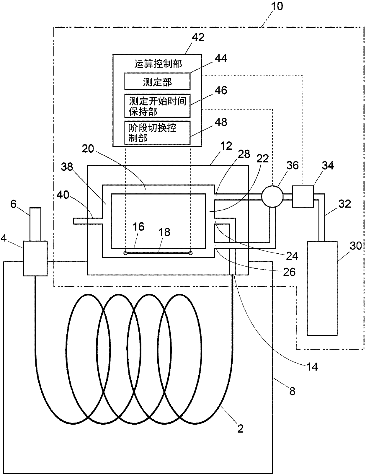
[0058] Hereinafter, an example of a thermal conductivity detector and a gas chromatograph including the thermal conductivity detector will be described with reference to the drawings.

[0059] First, use figure 1 A gas chromatograph of an example and a thermal conductivity detector used in the gas chromatograph will be described.

[0060] In the gas chromatograph, a sample vaporizer 4 is connected to one end of an analytical column 2 for separating a sample into components, and a detector 10 is connected to the other end of the analytical column 2 . The analytical column 2 is accommodated in the column heating furnace 8 and its temperature is adjusted. A syringe 6 is provided in the sample vaporization unit 4 , and the sample injected from the syringe 6 is vaporized in the sample vaporization unit 4 and guided to the analysis column 2 together with the carrier gas supplied to the sample vaporization unit 4 . The sample gas introduced into the analytical column 2 is separated...


PUM


Abstract

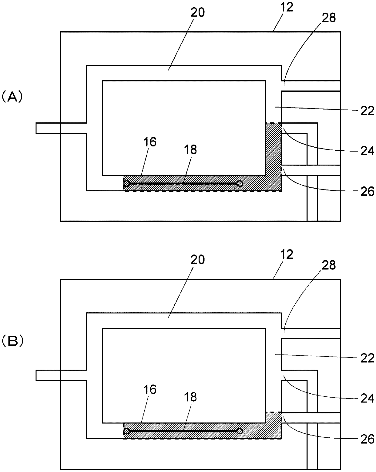
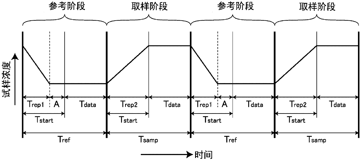
The invention provides a thermal conductivity detector and a gas chromatograph. Detection sensitivity of a single-filament thermal conductivity detector is to be increased. A thermal conductivity detector is a single-filament thermal conductivity detector, and includes a measurement cell, a phase switching mechanism, and a measurement section. The measurement section starts measurement of thermalconductivity of a sample gas after a lapse of a sample gas measurement start time that is set in advance, after a reference phase is switched to a sample phase by the phase switching mechanism, and starts measurement of thermal conductivity of a reference gas after a lapse of a reference gas measurement start time that is set in advance as a length of time different from the sample gas measurementstart time, after the sample phase is switched to the reference phase by the phase switching mechanism.

Description

technical field [0001] The present invention relates to a thermal conductivity detector and a gas chromatograph equipped with the thermal conductivity detector. Background technique [0002] The thermal conductivity detector detects the amount of change in the resistance value of the filament by flowing gas in the measurement flow path in which the filament is arranged, thereby obtaining the thermal conductivity of the gas flowing in the measurement flow path, and based on this, obtains Chromatogram. When gas flows in the measurement flow path in which the heated filament is arranged, the heat of the filament is taken away by heat conduction of the gas, and the resistance value of the filament changes. A chromatogram was obtained by measuring how much the resistance value of the filament when flowing a gas containing a sample (sample gas) changed from the resistance value when flowing a carrier gas not containing a sample (reference gas). [0003] In order to simultaneousl...

Claims


Application Information

Patent Timeline
Patent Type & Authority Applications(China)
IPC IPC(8): G01N30/66G01N30/02
CPCG01N30/02G01N30/66G01N25/18G01N27/18G01N2030/025G01N2030/126
Inventor 中间勇二
Owner SHIMADZU SEISAKUSHO LTD
Learn More