3.5-micron extreme-narrow linewidth laser output method

An output method and laser technology, applied in lasers, laser parts, phonon exciters, etc., can solve problems such as adverse effects of high-power operation of lasers, unbalanced thermal distribution, and constraints on theory and practice, and achieve labor-saving dimming. Cost, improve output performance, save adjustment time

Inactive Publication Date: 2018-03-16
HEILONGJIANG INST OF TECH
View PDF0 Cites 2 Cited by
  • Summary
  • Abstract
  • Description
  • Claims
  • Application Information

AI Technical Summary

Problems solved by technology

At present, single-doped Tm lasers basically adopt a single-end pumping method, which reduces the uniformity of laser crystal absorption of pump light, leads to unbalanced heat distribution inside the crystal, and adversely affects the high-power operation of the laser. The width is wider, and the transmission attenuation in the atmosphere is more obvious, which cannot meet the needs of military and civilian use.
[0003] In addition, the existing optical path adjustment technology is manual adjustment, it is difficult to obtain laser output with ideal pulse width, and only a single component can be adjusted at a time during manual adjustment, and it is difficult to obtain laser output with ideal pulse width
Therefore, in long-term scientific research, optical path adjustment has not only become a technical problem, but also the biggest obstacle restricting theory and practice.

Method used


Image

  • 3.5-micron extreme-narrow linewidth laser output method
  • 3.5-micron extreme-narrow linewidth laser output method

Examples


Embodiment Construction

[0015] In order to make the purpose, technical solutions and advantages of the present invention clearer, the present invention will be further described in detail below in conjunction with the accompanying drawings. Obviously, the described embodiments are only some of the embodiments of the present invention, rather than all of them. Based on the embodiments of the present invention, all other embodiments obtained by persons of ordinary skill in the art without making creative efforts belong to the protection scope of the present invention.

[0016] Preferred embodiments of the present invention will be described in detail below in conjunction with the accompanying drawings.

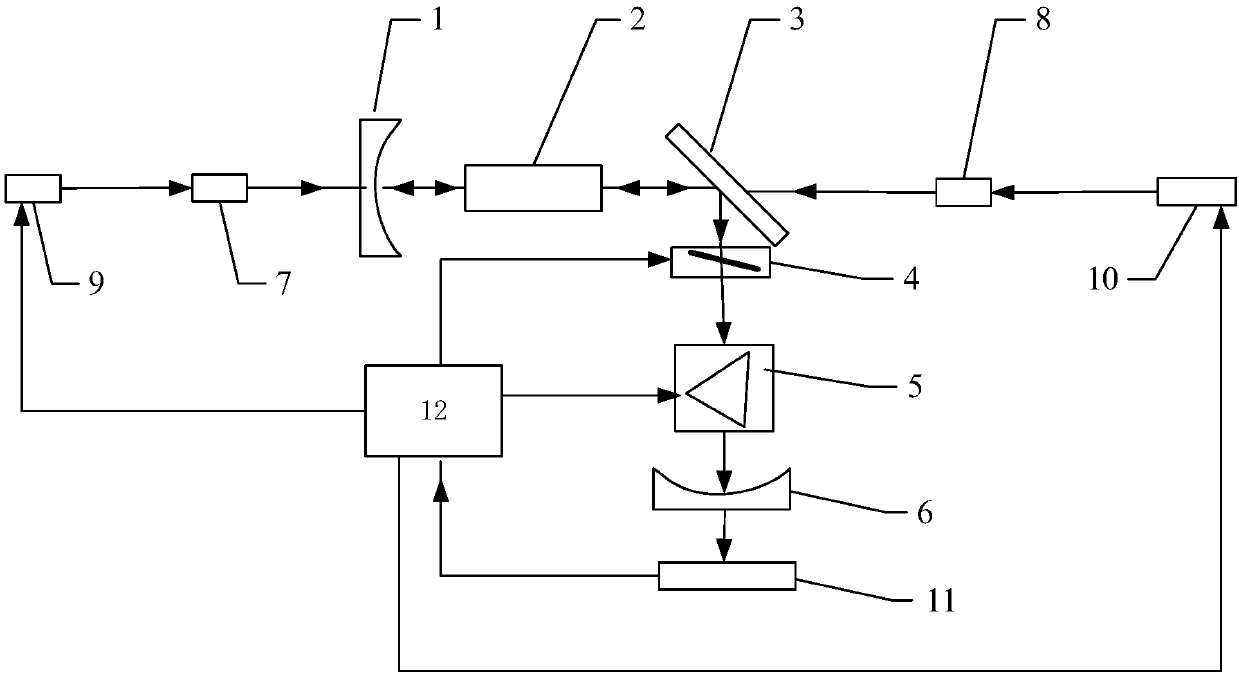
[0017] like figure 1 As shown, specifically, the present invention relates to a 3.5 micron ultra-narrow linewidth laser output method, including:

[0018] The 1.9 μm pumping light emitted by the first pump laser (9) is incident on the first isolating device (7), and the pumping light transmitted by th...


PUM


Abstract

The invention relates to a 3.5-micron extreme-narrow linewidth laser output method. 1.9-micron pumping light transmitted by a first pumping laser device (9) and a second pumping laser device (10) enters an isolation device, the pumping light transmitted through the isolation device enters a uni-doped Tm: YVO4 crystal (2) and is absorbed by the uni-doped Tm: YVO4 crystal (2), then 3.5-micron laseris produced, 2-micron obtained through total reflection conducted on the 3.5-micron laser by a second total reflection mirror (3) enters a graphene Bragg grating (4), and first compressed light is obtained through beam linewidth compression of the graphene Bragg grating (4). The first compressed light enters a quartz dispersing prism (5) performs second time of linewidth compression, compressed beams are output from an output coupling lens (6), a computer system (12) automatically adjusts parameters of the pumping lasers, optical grating and a prism till the performance of the output light ismatched with pre-stored simulation information, and accordingly laser output of picometer linewidth is obtained.

Description

technical field [0001] The invention relates to a laser output method with a 3.5-micron ultra-narrow line width, in particular to a laser output method with a pico-meter line width of 3.5 microns. Background technique [0002] Lasers in the 3-5μm band are widely used, involving military affairs, infrared remote sensing, medical treatment and optical communications, etc., especially the mid-to-far infrared laser output can be realized under the action of nonlinear conversion. At present, single-doped Tm lasers basically adopt a single-end pumping method, which reduces the uniformity of laser crystal absorption of pump light, leads to unbalanced heat distribution inside the crystal, and adversely affects the high-power operation of the laser. The width is wider, and the transmission attenuation in the atmosphere is more obvious, which cannot meet the needs of military and civilian use. [0003] In addition, the existing optical path adjustment technology is manual adjustment,...

Claims


Application Information

Patent Timeline
Patent Type & Authority Applications(China)
IPC IPC(8): H01S3/102H01S3/094
CPCH01S3/1022H01S3/094
Inventor 李林军段小明杨玉强杨曦凝白云峰谢文强周龙
Owner HEILONGJIANG INST OF TECH
Why Eureka
Try Eureka