
Surface heat sink of micro-nano composite structure and heat transfer enhancement method of surface heat sink

A micro-nano composite structure and enhanced heat transfer technology, applied in indirect heat exchangers, heat exchange equipment, lighting and heating equipment, etc., can solve the problem of reducing intermediate thermal resistance, high operating temperature of heating functional components, loss to air and Moderate problems in other media, to achieve the effect of reducing the surface temperature and enhancing the heat capacity of phase transformation

Pending Publication Date: 2018-03-20
INST OF ENGINEERING THERMOPHYSICS - CHINESE ACAD OF SCI
View PDF8 Cites 10 Cited by
  • Summary
  • Abstract
  • Description
  • Claims
  • Application Information

AI Technical Summary

Problems solved by technology

[0005] In view of the above-mentioned shortcomings in the prior art, the present invention provides a surface heat sink with a micro-nano composite structure and a method for enhancing heat transfer. Based on the basic principle of phase transformation heat at the micro-nano scale, the heat transfer capacity of the heat sink is improved. , so that the part of the electric energy converted into heat is quickly taken away from the high-temperature heat source in the form of liquid working fluid phase change, and finally lost to air and other media, greatly reducing the final medium (mainly air) from heat source to heat dissipation The intermediate thermal resistance is removed, which fundamentally solves the problem of high operating temperature of heating functional components

Method used


Image

  • Surface heat sink of micro-nano composite structure and heat transfer enhancement method of surface heat sink
  • Surface heat sink of micro-nano composite structure and heat transfer enhancement method of surface heat sink
  • Surface heat sink of micro-nano composite structure and heat transfer enhancement method of surface heat sink

Examples


Embodiment Construction

[0021] In order to make the object, technical solution and advantages of the present invention clearer, the present invention will be further described in detail below in conjunction with specific embodiments and with reference to the accompanying drawings.

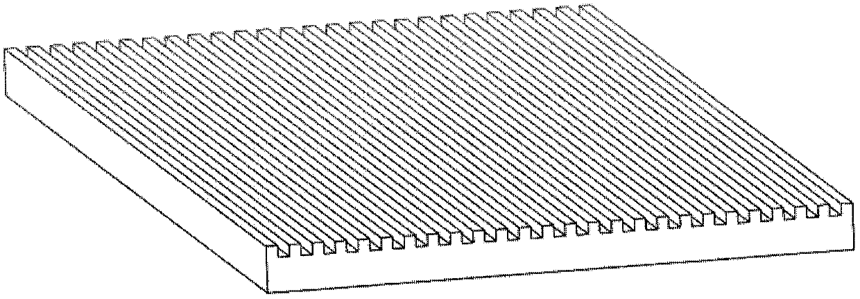
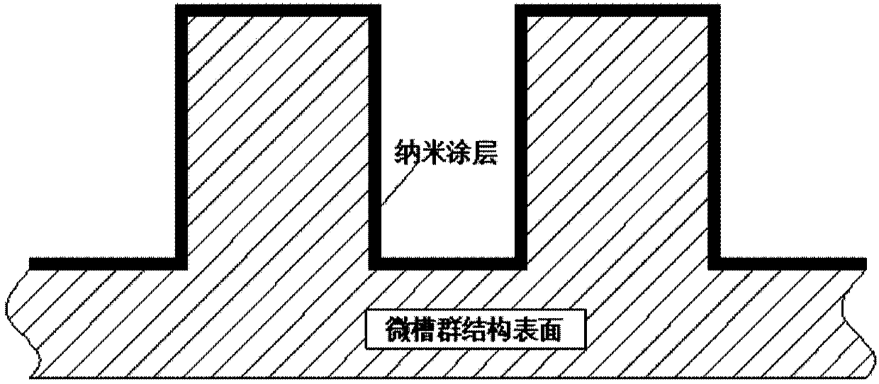
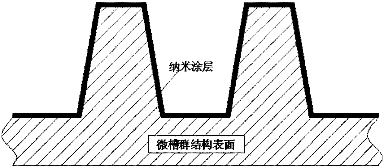
[0022] In order to solve the above problems, on the basis of the existing experimental research on surface heat sink phase change heat, the present invention further enhances the heat transfer design on the surface of the microgroove group heat sink from the perspective of surface optimization. Nano-scale material processing technology is applied to the surface of micro-groove heat sink to generate nano-coating. The special properties of nano-materials such as size effect and surface effect are applied, and the physical properties such as surface roughness, wettability, and surface energy of heat sink are changed. The phase-change heat capacity of the heat sink is improved by utilizing the affinity between the nano-coating...


PUM

PropertyMeasurementUnit
Thicknessaaaaaaaaaa
Widthaaaaaaaaaa
Depthaaaaaaaaaa

Abstract

The invention discloses a surface heat sink of a micro-nano composite structure and a heat transfer enhancement method of the surface heat sink, is used in the field of large power electronic integrated device heat exchanging, and solves the cooling problem of high heat flow density. The surface heat sink of the micro-nano composite structure comprises a micro groove group heat sink and a nanometer coating; the nanometer coating is generated on the surface of the micro groove group heat sink; a surface material of the micro groove group heat sink is a semiconductor, glass, ceramic or metal andan alloy of the metal; the micro groove cross section of the micro groove group heat sink is rectangular, trapezoidal or triangular; and a material of the nanometer coating is metal, a metal oxide, metal fluoride, a semiconductor material or organic high polymer paint. According to the surface heat sink of the micro-nano composite structure, the heat exchanging performance of the surface of the micro groove group heat sink is reinforced, and meanwhile, by means of the surface expanding and capillary acting force factors of the micro groove group structure, the phase changing heat exchanging capacity of the heat sink is improved.

Description

technical field [0001] The invention relates to the technical field of thermal energy engineering, in particular to a heat sink of a high-power electronic integrated device and a method for enhancing heat exchange thereof. Background technique [0002] With the development of high technology, the operating power of high-power electronic integrated devices including various computing processing chips, laser devices, high-power LED lamps, etc. is increasing. Among them, while these energy-consuming components exert effective power, a considerable part of the electric power is converted into heat, and the generation of heat will be accompanied by the temperature rise of these high-power electronic devices. However, high temperature is very detrimental to the operation of these high-power electronic devices. For example, if a high-power LED lamp does not add any heat sink, it will burn out after being powered on for a few seconds; the central processing unit (CPU) of a computer ...

Claims


Application Information

Patent Timeline
IPC IPC(8): F28D15/04F28F21/00
CPCF28D15/046F28F21/00
Inventor 胡学功栾义军
Owner INST OF ENGINEERING THERMOPHYSICS - CHINESE ACAD OF SCI
Learn More