
Heat dissipation device based on continuous droplet liquid supplementation

A heat dissipation device and liquid replenishment technology, which is applied in the direction of electrical components, electric solid devices, circuits, etc., can solve the problems of dry heating wall surface, inability to reduce the superheat of wall surface well, limited liquid replenishment capacity, etc.

Pending Publication Date: 2021-04-30
XI AN JIAOTONG UNIV
View PDF0 Cites 0 Cited by
  • Summary
  • Abstract
  • Description
  • Claims
  • Application Information

AI Technical Summary

Problems solved by technology

[0005] (1) When a single droplet hits the wall, the droplet cannot spread well on the entire heat transfer surface, and local overheating is prone to occur. Droplets with a high Weber (We) number are prone to splashing, bouncing and fragmentation. Can not reduce the superheat of the wall and increase the critical heat flux
[0006] (2) For porous and fast spray cooling of the heated wall, an additional power source needs to be added, the structure is cumbersome, and the corresponding cost is increased
[0007] (3) Thin-film evaporation mainly utilizes the rehydration ability of the evaporation-boiling capillary core (a square copper sheet with a microstructure on the surface) to replenish fluid from one side or all around, but its own fluid replenishment ability is limited, and the central area cannot be wetted in time. It can also cause local dry-out of the heating wall

Method used


Image

  • Heat dissipation device based on continuous droplet liquid supplementation
  • Heat dissipation device based on continuous droplet liquid supplementation
  • Heat dissipation device based on continuous droplet liquid supplementation

Examples


Embodiment Construction

[0036] Below in conjunction with accompanying drawing, the present invention is described in further detail:

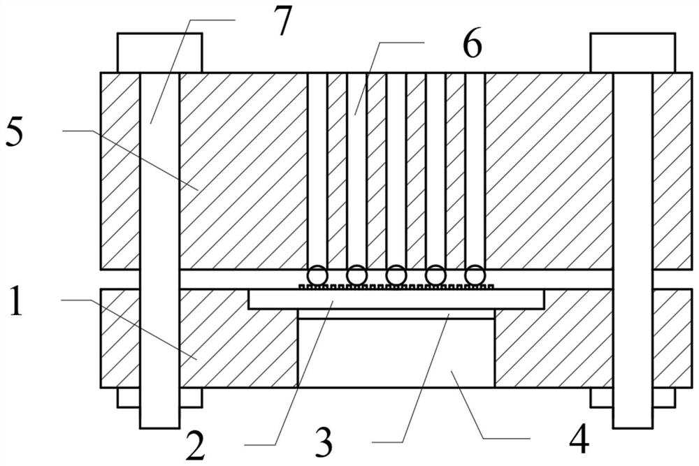
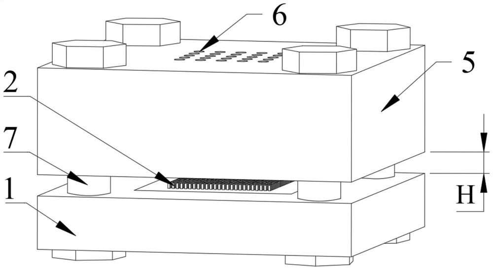
[0037] A heat dissipation device based on continuous liquid replenishment of droplets, such as Picture 1-1 , 1-2 As shown, it includes a lower substrate 1 , an evaporation-boiling capillary core 2 , an ITO heating film 3 , an insulating material 4 , a liquid replacement device 5 , a liquid replacement channel 6 , and a distance-adjustable stud 7 . An evaporation-boiling capillary wick 2 is arranged above the lower substrate 1, and an ITO heating film 3 is sputtered in the central area of ​​the bottom thereof, through which the ITO heating film 3 provides heat for the evaporation-boiling capillary wick 2, and the evaporation-boiling capillary wick 2 acts as a heat source. The bottom of the ITO heating film 3 is filled with an insulating material 4 to prevent heat exchange with the external environment and heat loss. A liquid replenisher 5 is arranged above, and a plura...


PUM

PropertyMeasurementUnit
Heightaaaaaaaaaa
Widthaaaaaaaaaa
Heightaaaaaaaaaa

Abstract

The invention discloses a heat dissipation device based on droplet continuous fluid infusion. The heat dissipation device mainly comprises a lower substrate, an evaporation boiling capillary core, a fluid infusion device, a distance adjusting stud and the like. The evaporation-boiling capillary core in the center area of the lower base plate serves as a heat source, an ITO heating film is sputtered at the bottom of the evaporation-boiling capillary core to supply heat to the evaporation boiling capillary core, a liquid supplementing device is arranged above the lower base plate, and liquid drops continuously supply liquid to the surface of the evaporation-boiling capillary core along a hydrophobic liquid supplementing channel, the diameter of the liquid supplementing channel being determined by the size of the liquid drops; the distance between the lower base plate and the liquid supplementing device is controlled through the distance adjusting stud, and liquid drops fall on the top of the evaporation boiling capillary core at the moment of leaving the liquid supplementing channel and are rapidly spread on the surface of the evaporation-boiling capillary core to form a layer of film, so that the superheat degree of the wall face is effectively reduced, and the critical heat flux density is greatly improved. The heat dissipation device has the advantages of being small in occupied area, low in power consumption and high in heat dissipation capacity, and can meet the heat dissipation requirement that the heat flow density exceeds 1,000 W / cm2.

Description

technical field [0001] The invention relates to the field of evaporation-boiling heat exchange in a small space, is suitable for high-efficiency electronic chip cooling technology, and particularly relates to a heat dissipation device based on continuous liquid replenishment of liquid droplets. Background technique [0002] Heat dissipation affects the reliability and life of chips and electronic equipment, and has become a bottleneck in the development of today's integrated circuit industry. Studies have shown that for every 10°C increase in the temperature of a single semiconductor component, the system reliability will be reduced by 50%, and more than 55% of electronic equipment failures are caused by excessive temperature. How to effectively dissipate the extremely high heat production per unit area and keep the peak temperature at a low level is an urgent problem to be solved in the development of chips and their components. [0003] The phase change technology utilizi...

Claims


Application Information

Patent Timeline
IPC IPC(8): H01L23/367H01L23/427
CPCH01L23/367H01L23/4275
Inventor 张永海马祥魏进家
Owner XI AN JIAOTONG UNIV
Learn More