Production process and molding equipment for 3D (three-dimensional) battery cover

A molding equipment and manufacturing process technology, applied in the direction of battery cover/end cover, battery pack components, battery box/jacket, etc., can solve the problems of damaged molding surface, easily damaged battery cover, no bright effect, etc. The effect of high molding yield and improving surface brightening effect

Pending Publication Date: 2018-03-20
FUJIAN SHISHI TONGDA ELECTRICAL APPLIANCE
View PDF13 Cites 9 Cited by
  • Summary
  • Abstract
  • Description
  • Claims
  • Application Information

AI Technical Summary

Problems solved by technology

[0004] In view of this, the object of the present invention is to provide a manufacturing process of a 3D battery cover to solve the problems of poor hardness, no bright effect and damaged molding surface of the exis

Method used


Image

  • Production process and molding equipment for 3D (three-dimensional) battery cover
  • Production process and molding equipment for 3D (three-dimensional) battery cover
  • Production process and molding equipment for 3D (three-dimensional) battery cover

Examples


Example Embodiment

[0030] In order to further explain the technical solution of the present invention, the present invention will be described in detail below through specific embodiments.

[0031] The manufacturing process of a 3D battery cover of the present invention is achieved through the following steps:

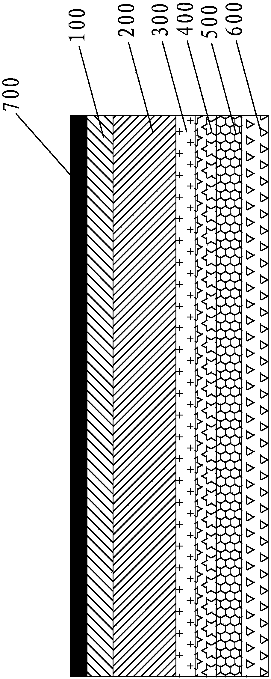
[0032] 1. Sheet composite, such as figure 1 As shown, the PMMA film 100 and the PC film 200 are compounded together to form a composite board, and the thickness of the PMMA film 100 is thinner than the thickness of the PC film 200, the PMMA film 100 is above the PC film 200, and the two completely overlap;

[0033] 2. Printing: A LOGO pattern printing layer 300 is printed on the bottom surface of the PC film 200, and then a UV transfer texture pattern layer 400 is transferred on the LOGO pattern printing layer 300 by UV glue, that is, using UV glue and UV printing process The pattern printing layer 300 is printed with a pattern texture, such as a grating texture, and then an optical film layer ...


PUM

PropertyMeasurementUnit
Thicknessaaaaaaaaaa

Abstract

The invention discloses a production process for a 3D (three-dimensional) battery cover. The production process is realized by the following steps: compounding a PMMA (Polymethyl Methacrylate) film with a PC (Polycarbonate) thin film to form a compound board; sequentially arranging a LOGO pattern printing layer, a UV(ultraviolet) transfer printing texture pattern layer, an optical film layer and abase color ink layer on the bottom surface of the PC thin film from top to bottom to form a to-be-molded sheet; putting the to-be-molded sheet on molding equipment for molding at high pressure to obtain a molded semi-finished product; carrying out shower coating of UV hardening liquid on the top of the surface of the molded semi-finished product by using a pressure gun; enabling the surface of the molded semi-finished product to be coated with the UV hardening liquid fully, and then drying to form a surface treatment part; cutting on the surface treatment part by reverse placement by using aCNC (Computer Numerical Control) cutter to form a finished product of the 3D battery cover. Compared with the prior art, the 3D battery cover has the advantages that the battery cover also has good toughness and higher hardness on the premise of reaching excellent strength as well as high rate of the molded finished product and highlight effect of the surface. The invention also discloses moldingequipment for the 3D battery cover.

Description

Technical field [0001] The invention relates to the field of manufacturing of mobile phone accessories, in particular to a manufacturing process of a 3D battery cover and a molding device used for 3D battery cover molding. Background technique [0002] Most of the battery covers of various communication electronics and household appliances on the market are made of plastic materials. At the same time, in order to prevent the surface pattern from being scratched, the pattern layer is generally set on the back of the battery cover, so that the pattern can keep the color vivid for a long time. Fading, this is also what the society wants. In order to enhance the appearance effect of the battery cover, UV varnish is usually used for repeated overlay printing to achieve the purpose of presenting a three-dimensional pattern effect. However, the battery cover made of this plastic material has a slightly lower hardness and cannot show a bright effect. At the same time, the traditional pl...

Claims


Application Information

Patent Timeline
IPC IPC(8): H01M2/04B32B27/08B32B27/36B32B33/00B32B37/10H01M50/147
CPCB32B27/08B32B27/36B32B27/365B32B33/00B32B37/10H01M50/147Y02E60/10
Inventor 林双福喻爱平林键辉
Owner FUJIAN SHISHI TONGDA ELECTRICAL APPLIANCE
Why Eureka
Try Eureka