A handheld ultrasound device and imaging method

An imaging method and ultrasonic technology, applied in the directions of ultrasonic/sonic/infrasonic image/data processing, ultrasonic/sonic/infrasonic diagnosis, acoustic diagnosis, etc., can solve problems such as performance degradation, limited application range, and image quality reduction, and achieve Reduces power consumption, prolongs battery life, and prevents the device from overheating

Active Publication Date: 2018-11-09
武汉启佑生物医疗电子有限公司
View PDF8 Cites 0 Cited by
  • Summary
  • Abstract
  • Description
  • Claims
  • Application Information

AI Technical Summary

Problems solved by technology

If the power consumption of a handheld ultrasound device is too high, it will cause the device to overheat or have a short battery life; therefore, how to control power consumption is the primary problem faced by this type of handheld ultrasound device
Products currently on the market mainly limit power consumption in two ways: one is to reduce performance, including function limitations, image quality, and channels; the other is to limit continuous working time to prevent the probe from overheating
[0005] These two methods have their obvious shortcomings: the first one controls power consumption by reducing performance, which limits the application range of such products; the second one controls power consumption by limiting continuous working time, which causes additional problems for operators the inconvenience

Method used


Image

  • A handheld ultrasound device and imaging method
  • A handheld ultrasound device and imaging method
  • A handheld ultrasound device and imaging method

Examples


Embodiment 1

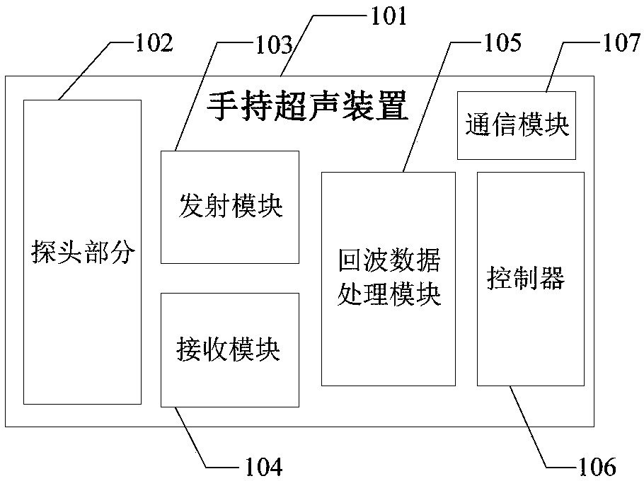
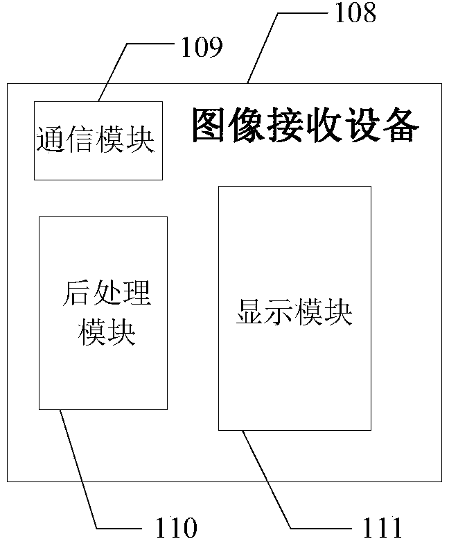
[0081] This embodiment provides a handheld ultrasonic device, such as Figure 1a As shown, it includes: a probe part 102, a transmitting module 103, a receiving module 104, an echo data processing module 105, a controller 106 and a communication module 107; the controller 106 controls the transmitting module 103 to generate a transmitting pulse to excite the The probe part 102 transmits an ultrasonic signal; the controller 106 controls the receiving module 103 to collect the ultrasonic echo signal received by the probe part 102; the echo data processing module 105 collects the ultrasonic echo signal collected by the receiving module 103 After the wave signal is processed, the data is sent to the communication module 107; the communication module 107 communicates with the external image receiving device 108 in a wireless or wired manner.

[0082] The controller 106 performs low-power scanning control on the transmitting module 103 and the receiving module 104, and the low-power ...

Embodiment 2

[0103] The difference between this embodiment and Embodiment 1 is that this embodiment specifically describes the C-mode imaging method, and the specific method flow chart is shown in the attached Figure 5 Shown:

[0104] In this embodiment, mode C adopts a scanning mode in which one frame B and one frame C are alternately scanned;

[0105]501. Set the number of scans of B frame B under C mode as N0 and the number of B empty scans as N01; the N01 only needs to meet the minimum time requirement of B frame under C mode; the minimum time requirement is determined by the controller 106 of the device of the present invention ;

[0106] 502. Calculate the single C scan period t1 according to the relevant parameters of the C mode and the current state of the color sampling frame;

[0107] 503. Set within the single C scan period t1, the transmitting module is only valid when transmitting, and the receiving module is only valid when receiving the data in the current color sampling ...

Embodiment 3

[0121] The difference between this embodiment and Embodiment 1-2 is that this embodiment specifically describes the D-mode imaging method, and the specific method is as follows Figure 6 Shown:

[0122] 601. Calculate a single D scan period t2 according to the relevant parameters of the D mode and the currently measured blood flow velocity V;

[0123] 602. Set within a single D-scan period t2, the transmitting module is only valid when transmitting, and the receiving module is only valid when receiving data in the current pulse Doppler sampling frame. During the invalid time, the corresponding module enters a low power consumption state;

[0124] 603. After measuring the total power consumption W2 of the transmitting module and the receiving module of the device of the present invention,

[0125] 604. If W2 does not exceed the preset maximum power consumption Y2, go to 605; otherwise, go to the next step 606;

[0126] 605. End of setting;

[0127] 606. Reduce the currently ...


PUM


Abstract

The invention relates to a handheld ultrasonic device and an imaging method. The device comprises a probe part, a transmitting module, a receiving module, an echo data processing module, a controllerand a communication module; the controller controls the transmitting module to generate transmission pulses so that the probe part can be stimulated to transmit ultrasonic wave signals; the controllercontrols the receiving module to collect ultrasonic echo signals received by the probe part; the echo data processing module processes the ultrasonic echo signals collected by the receiving module and then sends the data to the communication module; the communication module communicates with external image receiving equipment in a wireless or wired mode; the controller conducts low-power-consumption scanning control on the transmitting module and the receiving module, wherein low-power-consumption scanning control comprises the steps that the transmitting module is controlled to conduct widening transmission, the receiving module is controlled to conduct widening receiving, it is controlled that low-power-consumption empty scanning is generated, the transmitting module is controlled to work during ultrasonic transmission, and the receiving module is controlled to work when receiving effective data. According to the device and the method, on the basis that the system performance is notdegraded, power consumption is reduced, probe overheating is prevented, and endurance time is prolonged.

Description

technical field [0001] The invention relates to a handheld ultrasonic device and an imaging method. Background technique [0002] In traditional ultrasonic equipment, the main body of the probe part is the ultrasonic transducer, which mainly realizes the conversion of electrical signals and ultrasonic signals, including converting high-voltage emission pulses into ultrasonic waves and converting ultrasonic echoes into echo electrical signals; The signal is then transmitted to the ultrasonic host through the cable for processing. Traditional ultrasound trolley equipment is powerful, but bulky; with the expansion of ultrasound application fields, more and more low-performance portable ultrasound equipment has appeared on the market. These equipment can be hand-held or hand-held, but the system structure , which is basically the same as the traditional trolley equipment, and the ultrasonic probe is connected to the host computer through a cable. [0003] In recent years, a mo...

Claims


Application Information

Patent Timeline
Patent Type & Authority Patents(China)
IPC IPC(8): A61B8/00
CPCA61B8/4427A61B8/4472A61B8/52
Inventor 李腾飞胡则肄
Owner 武汉启佑生物医疗电子有限公司
Why Eureka
Try Eureka