
Positioning instrument for high-speed trochlear shaped subchondral bone abrasive drilling
A subchondral bone and locator technology, applied in bone drill guidance, medical science, surgery, etc., can solve problems such as inability to complete trochlea forming, poor control of uniformity, damage to articular cartilage, etc., and achieve light weight, comprehensive mechanical Good performance and balanced force effect
- Summary
- Abstract
- Description
- Claims
- Application Information
AI Technical Summary
Problems solved by technology
Method used
Image

Examples
Embodiment 1
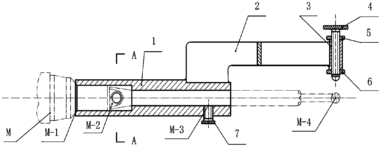
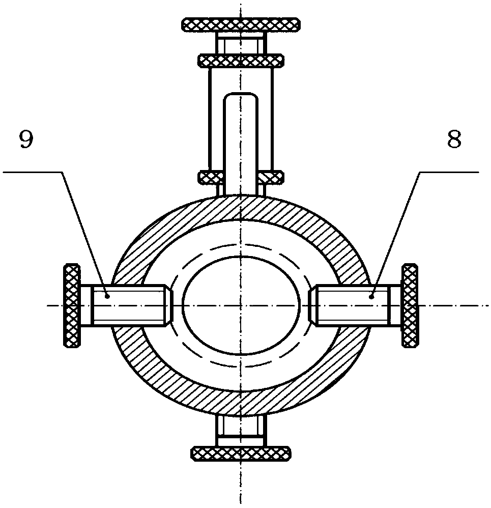
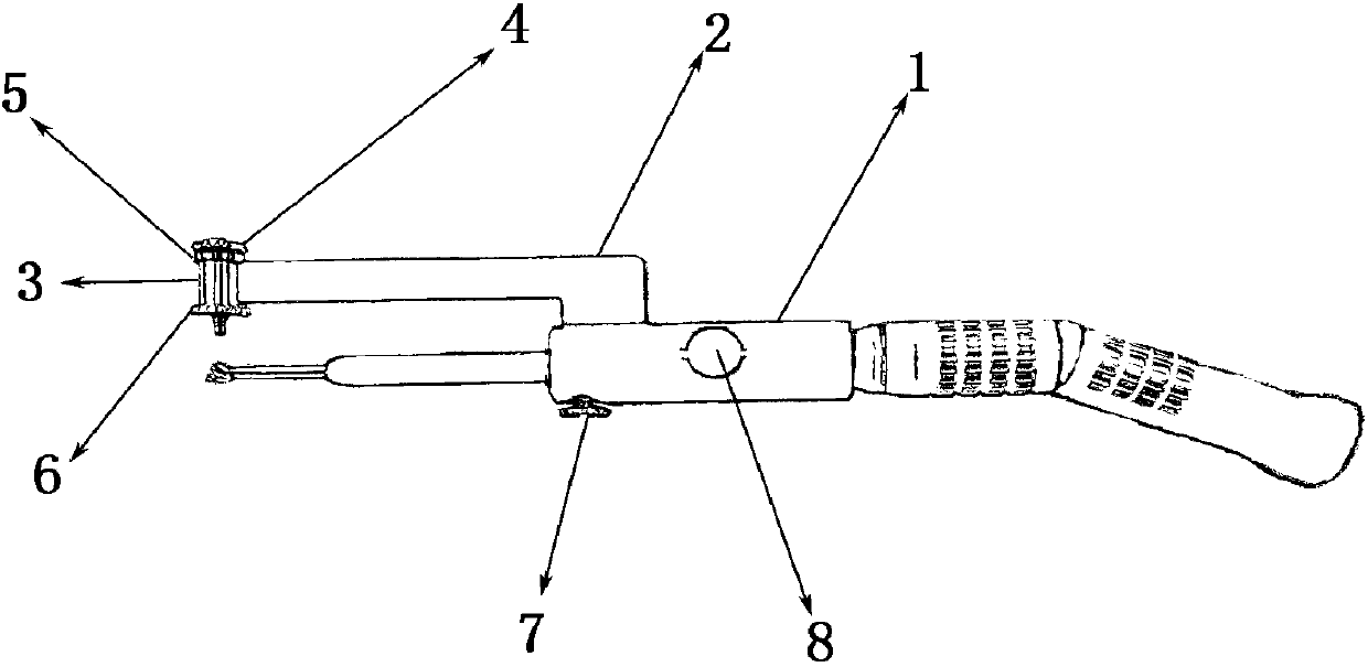
[0037] A positioner for high-speed grinding and drilling of subchondral bone formed by a pulley, comprising: a sleeve 1, a force arm 2, a cylindrical guide block 3, a round head guide stud 4, a lock nut A5, a lock nut B6, a round head clamp Fixing screw A7, round head fastening screw B8 and round head fastening screw C9, one end of the described moment arm 2 is fixedly connected with the described sleeve 1, and the other end of the described moment arm 2 is fixed with the described cylindrical guide block 3 connection, the round head guide stud 4 passes through the lock nut A5, the cylindrical guide block 3 and the lock nut B6 respectively, and the round head fastening screw A7, the round head fastening screw B8 and the round head fastening screw B8 are installed on the sleeve 1 head fastening screw C9.
[0038] The round-head fastening screw A7 is installed under the sleeve 1, the round-head fastening screw B8 and the round-head fastening screw C9 are installed on both sides ...
Embodiment 2
[0053] Embodiment 1 is explained and supplemented, the principle of the present invention is, under the premise of not changing the shape, size and basic functions of the high-speed grinding drill used in hospital orthopedic surgery, it can be installed (disassembled) and limited along the horizontal axis, radially Force clamping, conical (column) surface positioning, adjust the distance between the high-speed grinding and drilling grinding head M-4 and the round head guide stud 4 hemispherical head along the vertical axis, thread fastening and laser welding, manual tightening ( release).
[0054] The developed positioner for high-speed grinding and drilling of subchondral bone with pulley forming has the advantages of simple structure, reasonable positioning, firm clamping, convenient disassembly and assembly, light and corrosion-resistant, safe and reliable, and the distance between the grinding head and the hemispherical head of the guide stud is convenient. adjustment feat...
Embodiment 3
[0065] When applied to specific operations, surgical requirements: patients with recurrent patellar dislocation caused by trochlear dysplasia (type B trochlear), need to undergo trochlear forming subchondral bone surgery, during the operation, high-speed grinding drills are used for subchondral bone grinding, grinding When the grinding wheel grinding head and the articular surface should maintain a distance of 4mm.
[0066] The steps to use the locator are as follows:
[0067] (1) Install high-speed grinding drill with positioner
[0068] a. The two sides of the holding force arm 2 are parallel to the two sides of the small cone in the middle of the high-speed grinding drill M and are parallel to the triangular plane M-2. Put the sleeve 1 axially on the front part of the high-speed grinding drill M with the installed grinding head and stick to the large tapered surface M-1 in the middle of the high-speed grinding drill.
[0069] b. Manually turn fastening screws 8, 9, and 7 ...
PUM
 Abstract
Description
Claims
Application Information