

Photoelectric composite medium-voltage fireproof lock type cable
A photoelectric composite, fire-proof lock technology, applied in power cables, power cables with shielding/conductive layers, insulated cables, etc. The effect of high locking force
- Summary
- Abstract
- Description
- Claims
- Application Information
AI Technical Summary
Problems solved by technology
Method used
Image

Examples
Embodiment 1
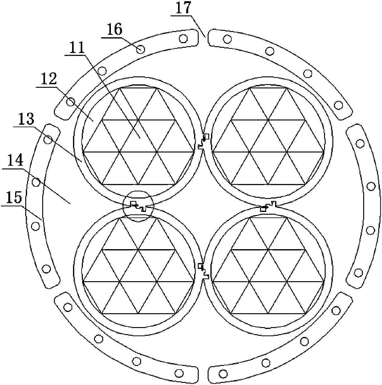
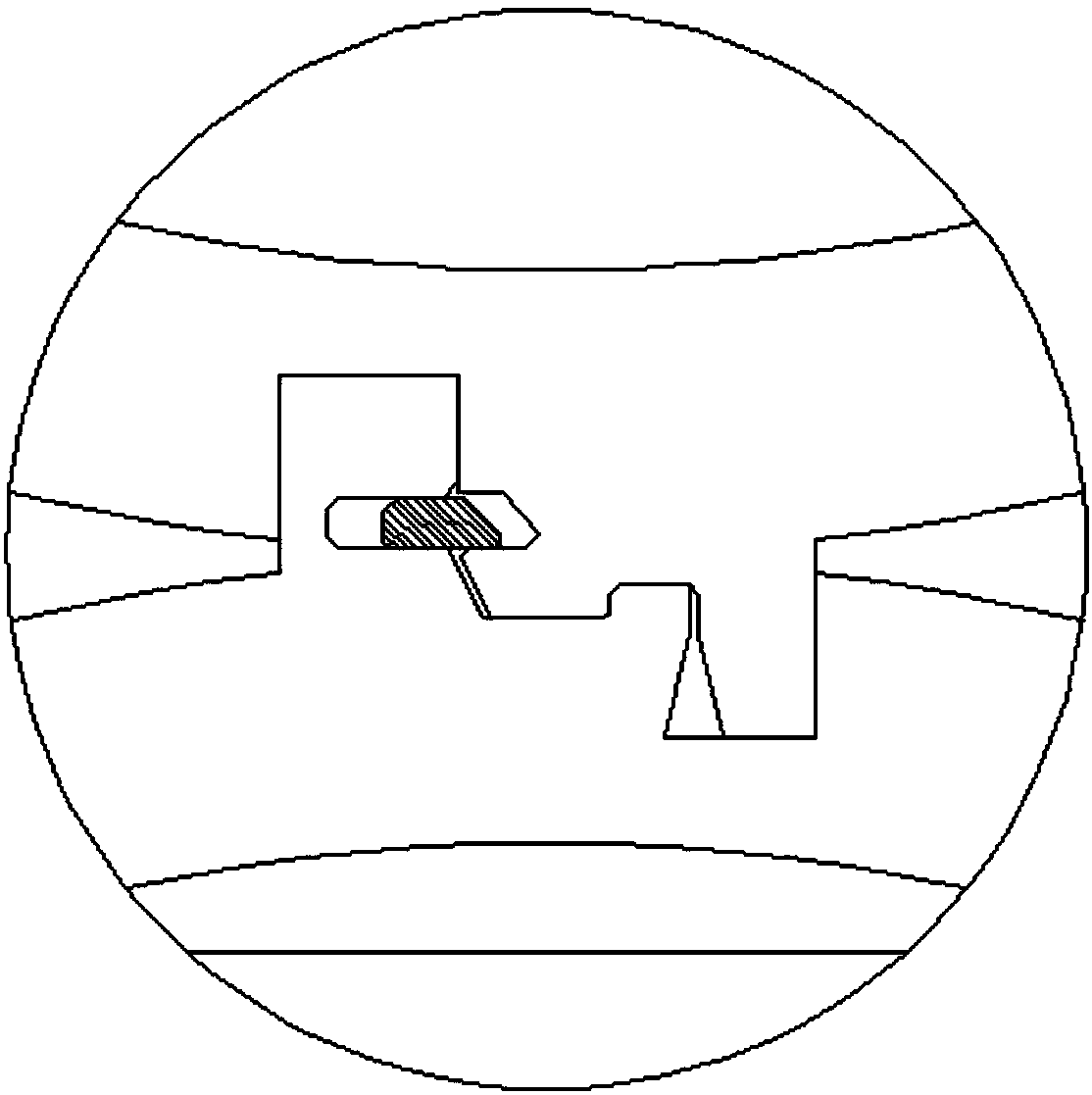
[0022] A photoelectric composite medium-voltage fireproof lock type cable. The cable includes a cable core composed of multiple wire cores. The cable core is wrapped with a protective layer. The first filling layer is filled between the cable core and the protective layer. The layer protects the core inside it. Each strand of wire core includes multiple groups of core materials and insulating layers wrapped outside the multiple groups of core materials. Multiple groups of core materials may be distributed around the group core material. Multiple groups of core materials are wrapped with insulating layers, and the gap between the core materials and the insulating layers is filled with a second filling layer, which can cause interference between multiple groups of wire cores through the insulating layers. Of course, an insulating layer can also be provided outside each group of core materials, and the insulating layer on the core material is separated from the rest of the core ...
Embodiment 2
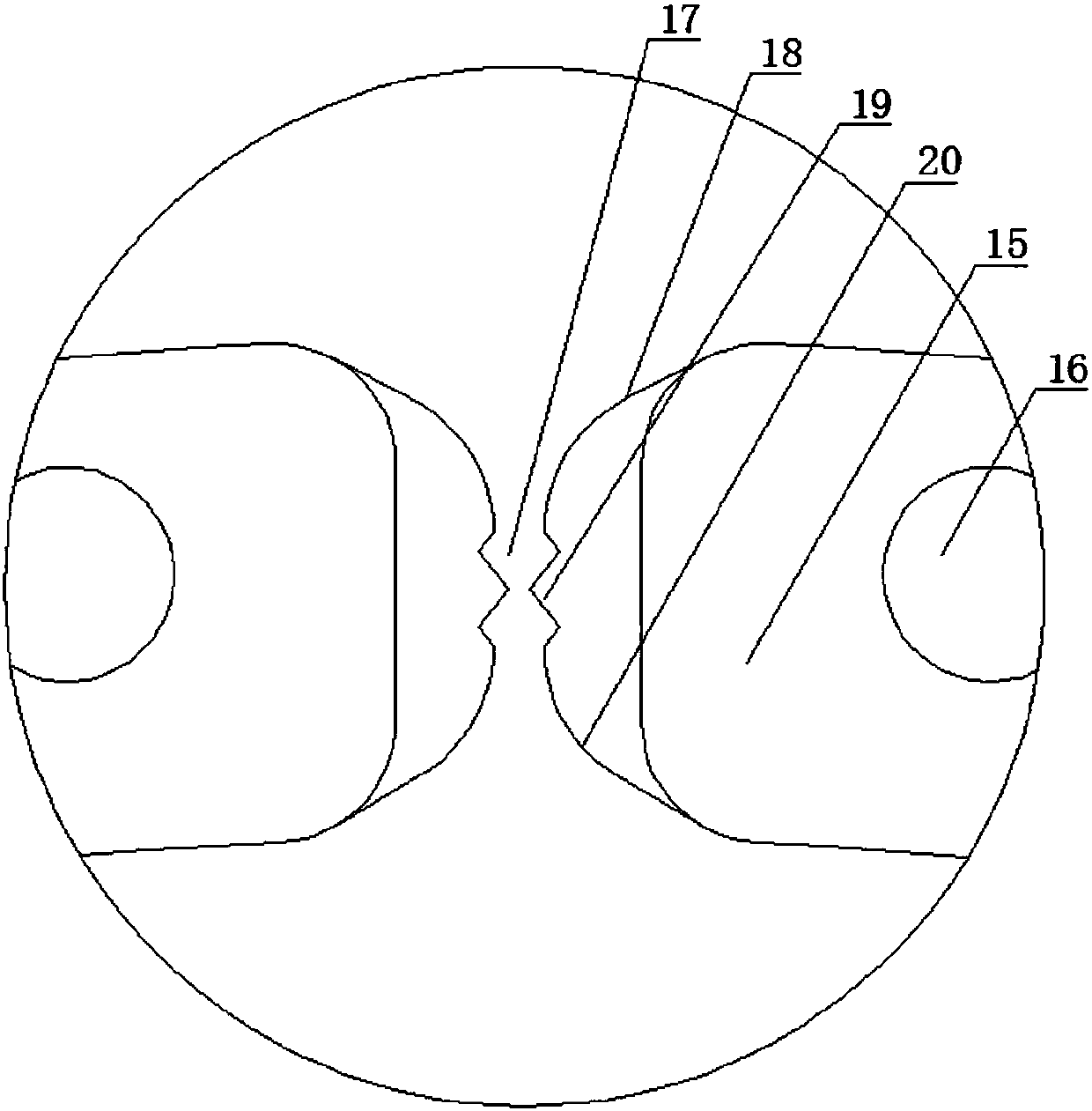
[0026] On the basis of Embodiment 1, there are cooling holes on the protective layer. The cooling holes include an inner polyurethane flame-retardant and waterproof layer connected to the inner side of the protective layer, an outer polyurethane flame-retardant and waterproof layer connected to the outer side of the protective layer, and an inner polyurethane flame-retardant and waterproof layer. A spring cord is connected between the layer and the outer polyurethane flame-retardant waterproof layer. There are heat dissipation holes on the protective layer, and the inner polyurethane flame-retardant and waterproof layer and the outer polyurethane flame-retardant and waterproof layer are arranged in the heat dissipation holes, so as to avoid the damage caused by the intrusion of external water vapor into the cable.
Embodiment 3
[0028]On the basis of Embodiment 1 or Embodiment 2, the protective layer includes a polyethylene-filled vulcanized insulating layer, a copper wire braided shielding layer, an aluminum halogen-free low-smoke flame-retardant polyolefin bonded protective layer, and an aluminum-free Halogen-free low-smoke flame-retardant polyolefin bonding protective layer mainly utilizes the characteristics of halogen-free low-smoke flame-retardant polyolefin materials that do not contain halogens and other heavy metals such as lead, cadmium, chromium, mercury, etc. Even if it is burned, it will not produce toxic smoke such as halogenated Hydrogen, and no corrosive gas is released, and the smoke produced is also very small.
PUM
 Abstract
Description
Claims
Application Information